Uniform heat dissipating and cooling heat sink

a heat sink and heat dissipation technology, applied in the direction of semiconductor/solid-state device details, lighting and heating apparatus, laminated elements, etc., can solve the problems of uneven cooling and heat dissipation of components, damage to the component itself and/or other adjacent components, uneven cooling of the heat sink itself, etc., to reduce air flow turbulence, reduce air flow resistance, increase air flow velocity

Inactive Publication Date: 2005-09-13
DEGREE CONTROLS
View PDF43 Cites 49 Cited by
  • Summary
  • Abstract
  • Description
  • Claims
  • Application Information

AI Technical Summary

Benefits of technology

The invention provides a heat sink that can dissipate heat evenly and cool the device it is attached to. It also reduces air resistance, increases air flow velocity, and decreases air flow turbulence.

Problems solved by technology

Modern electronics components generate large amounts of heat that must be removed through heat sinking. Heat sinks usually require a certain amount of space and are designed with a constant cross-sectional area. This results in uneven cooling of different parts of the component, causing warming or even failure of the component. Prior art heat sinks may also lack optimal aerodynamic efficiency due to their design. Therefore, there is a technical problem in developing improved heat sink designs that address issues related to heat transfer mechanisms (conduction and convection) while optimizing space usage and enhancing cooling efficiency.

Method used


Image

  • Uniform heat dissipating and cooling heat sink
  • Uniform heat dissipating and cooling heat sink
  • Uniform heat dissipating and cooling heat sink

Examples


Embodiment Construction

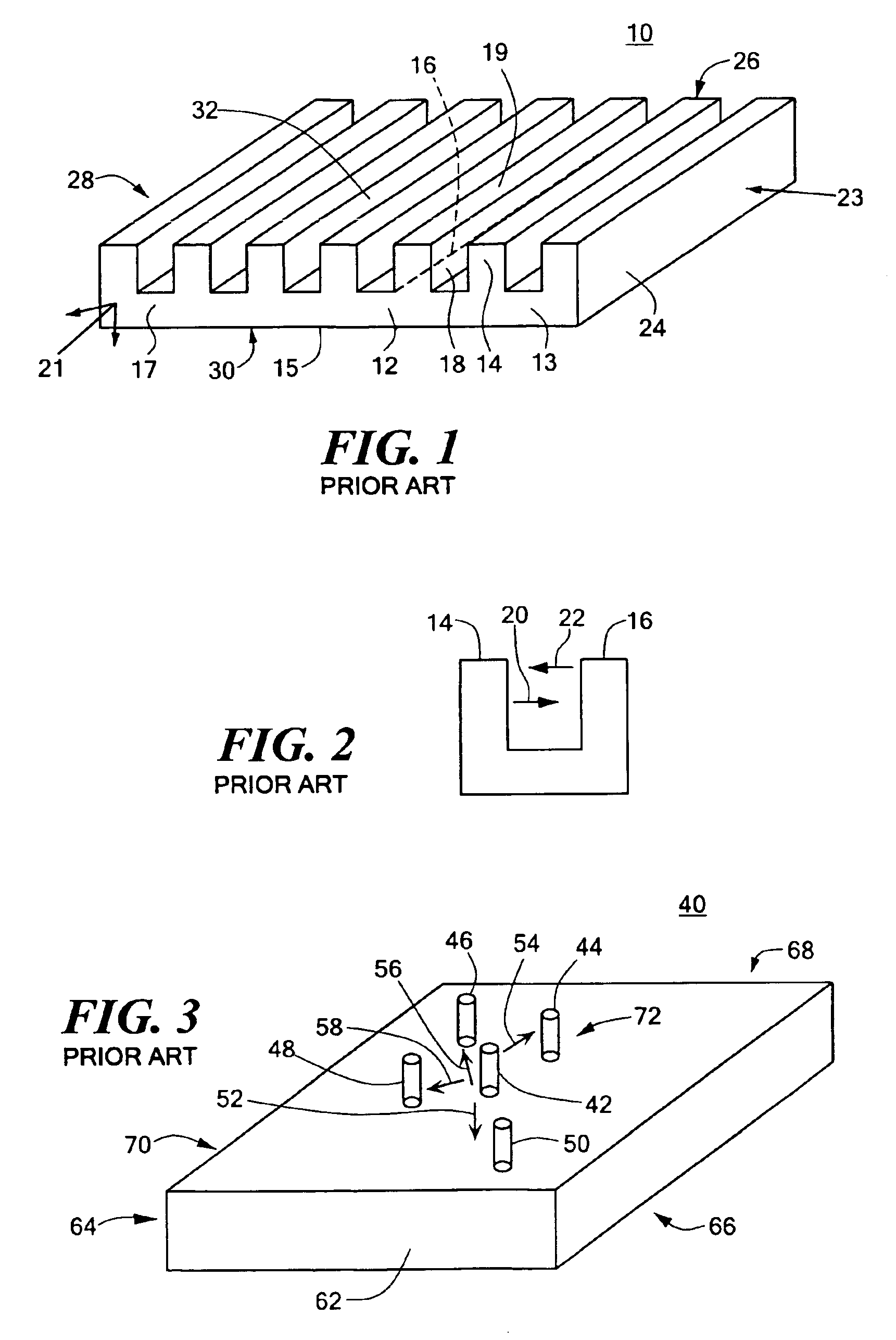
[0044]As explained in the Background of the Invention section above, typical prior art heat sink 10 includes uniform thickness body 12, upstanding fin 14 and adjacent fin 16 separated by flow channel 18. This design, however, has several distinct disadvantages. Because edges 24, 26, 28, and 30 of body 12 have a greater surface area exposed to the ambient air than interior portion 32, edges 24, 26, 28, and 30 cool faster by convection than interior portion 32. The result is uneven heat dissipation and cooling of any component affixed to heat sink 10 which can cause warping, cracking and malfunctioning of the component the heat sink is designed to cool.

[0045]Another disadvantage with prior art heat sink 10 is that heat from each fin is projected toward all adjacent fins. As shown in FIG. 2, heat radiating from upstanding fin 14, shown as arrow 20, is projected toward adjacent fin 16. Similarly, heat radiating from fin 16 is projected toward upstanding fin 14 as shown by arrow 22. The ...


PUM


Abstract

A uniform heat dissipating and cooling heat sink for increasing conductive cooling at locations where conductive cooling and temperature differential is reduced. The heat sink includes a base having a variable thickness with a maximum thickness at the interior thereof and a plurality of fins upstanding from the base with adjacent fins separated by a flow channel having diverging sides.

Description


Claims


Application Information

Patent Timeline
Owner DEGREE CONTROLS
Why Eureka
Try Eureka