Coaxial plasma arc vapor deposition apparatus and method

a plasma arc and vapor deposition technology, applied in vacuum evaporation coatings, electrolysis components, coatings, etc., can solve the problems of forming objectionable irregularities and generating droplets of molten target materials

Inactive Publication Date: 2011-01-11
KRISHNAN MAHADEVAN
View PDF27 Cites 46 Cited by
  • Summary
  • Abstract
  • Description
  • Claims
  • Application Information

AI Technical Summary

Benefits of technology

[0016]A first object of the invention is an apparatus for the deposition of a variable thickness of...

Problems solved by technology

An undesirable side effect of the vaporization of the target material at the arc spot is the generation of droplets of molten target material, which are ejected from the targ...

Method used


Image

  • Coaxial plasma arc vapor deposition apparatus and method
  • Coaxial plasma arc vapor deposition apparatus and method
  • Coaxial plasma arc vapor deposition apparatus and method

Examples


Embodiment Construction

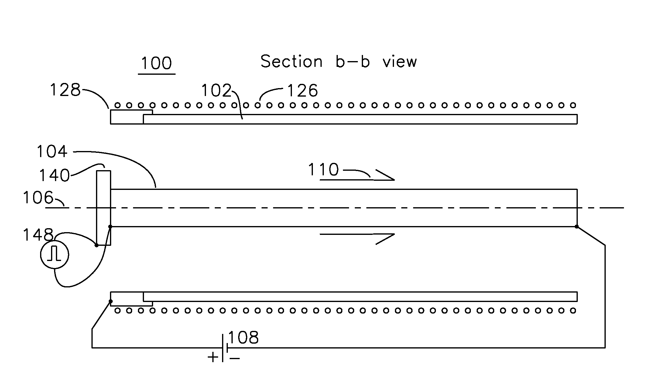
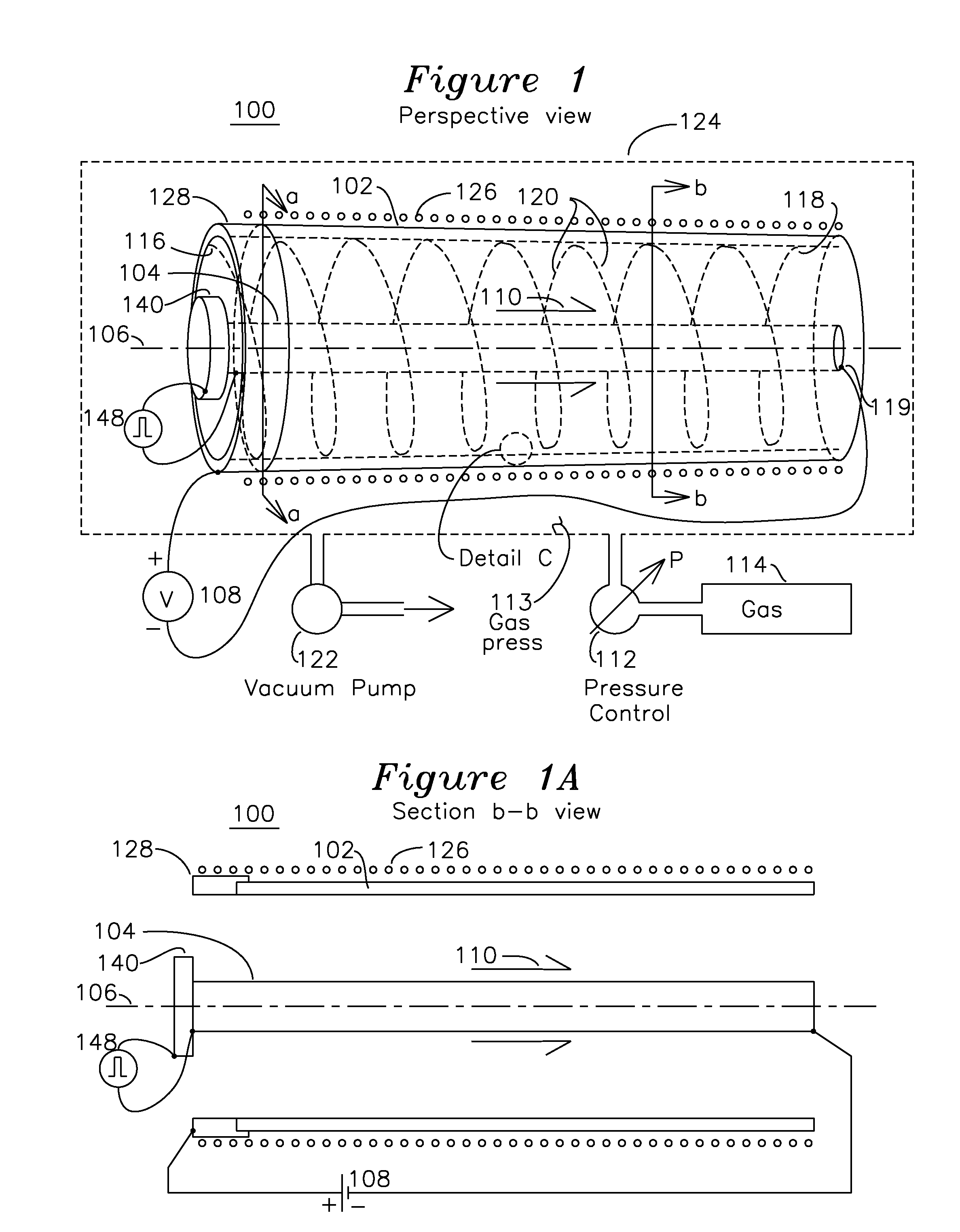
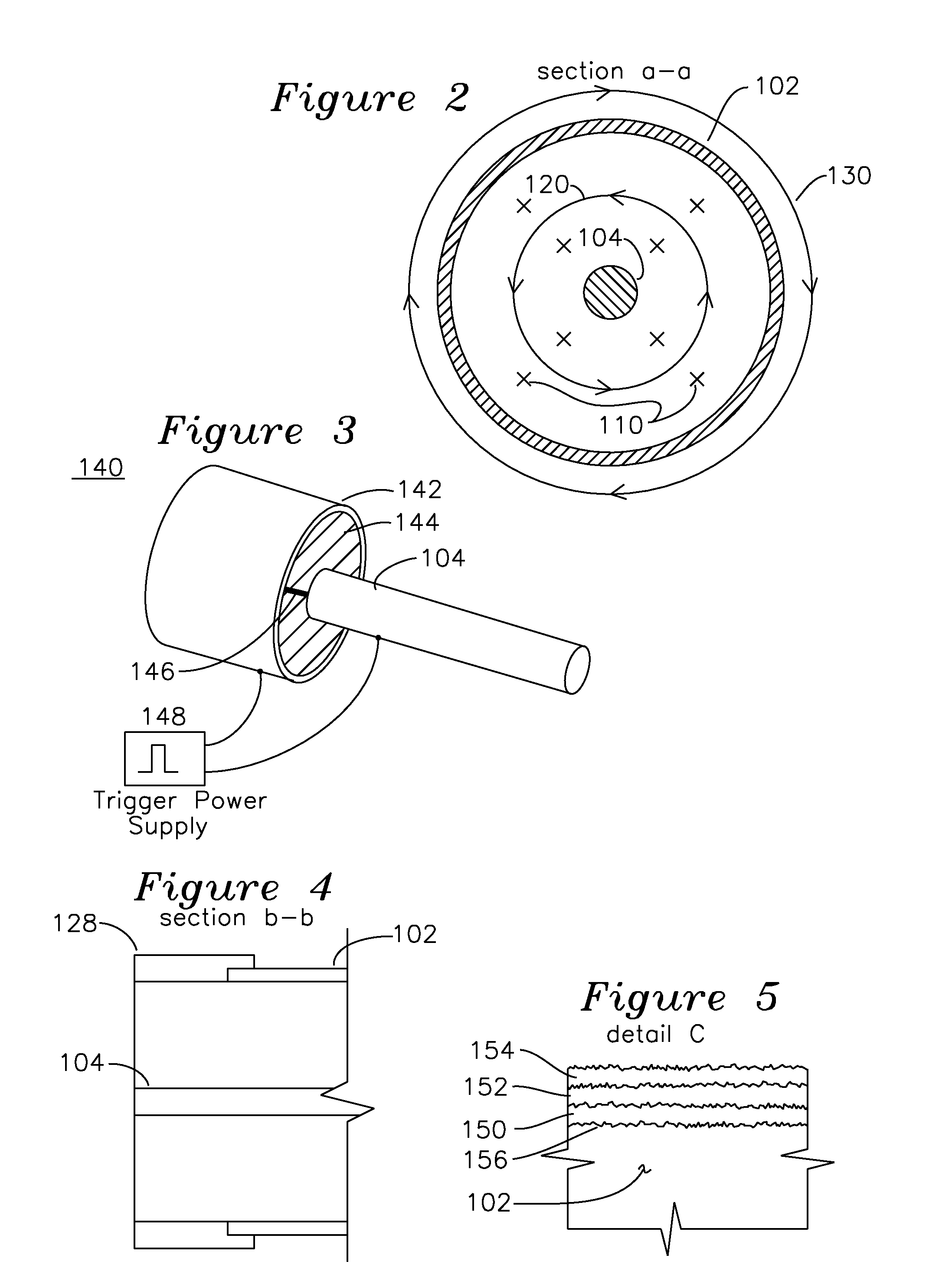
[0028]FIG. 1 shows a perspective view of a coaxial plasma arc deposition system 100, shown also in section b-b view as FIG. 1A, the plasma arc deposition system 100 comprising a chamber 124, a vacuum pump 122, a source of gas 114, a pressure control valve 112, and a cylindrical anode 102, which is to have an inner surface coated by material contributed by a cathode 104. Surrounding the anode 102 is a magnetic B field 110 generated by coil 126 which creates a magnetic field 110 parallel to the central axis 106. Placed substantially on the central axis 106 is the cathode 104, which is formed from the material to be deposited on the inside of the anode 102. A voltage source 108 is applied with a positive potential on the anode 102 and a negative potential on the cathode 104. A plasma arc initiator 140 initiates a plasma arc near a start point 116 on one end of the anode 102, and once initiated, the plasma follows a helical path 120 until it reaches end point 118 on the opposite end of ...


PUM

PropertyMeasurementUnit
Electrical resistanceaaaaaaaaaa
Thicknessaaaaaaaaaa
Pressureaaaaaaaaaa

Abstract

An apparatus for the deposition of a variable thickness coating onto the inside of a cylindrical tube comprises a variable pressure gas, an cathode coaxially positioned within the cylinder, and a voltage source applied between the cathode and cylindrical tube, which functions as an anode. A radial plasma arc is generated between the anode and cathode at a starting point on the cylinder, and the plasma arc travels down the central axis of the cylinder, providing a helical deposition region on the inside of the cylinder. Selection of the combination of cathode material and gas enable the plasma to generate ionic material which is deposited on the anodic cylinder in the region of the plasma. By varying the pressure of variable pressure gas for each helical path, it is possible to vary the composition of this deposition film.

Description

FIELD OF THE INVENTION[0001]The invention pertains to the use of a rotating plasma for the deposition of ceramic and metal materials onto a conductive cylindrical surface. In particular, the composition of the deposition over the inner surface of a cylinder may be controlled such that the composition of the coating may be varied through the thickness of the coating.BACKGROUND OF THE INVENTION[0002]This invention relates generally to the coating of substrates using vacuum arc evaporation, and more particularly to an improved method and apparatus that employs a cylindrical metallic cathode and a magnetic field interacting with a plasma arc to cause the plasma arc to follow a helical trajectory on the surface of the cylindrical cathode.[0003]Vacuum arc evaporation can be used for deposition of metal, alloy, and metal compound coatings. A cathode composed of the material to be deposited is vaporized by a high current, low voltage arc plasma discharge in a vacuum chamber, which has been ...

Claims


Application Information

Patent Timeline
IPC IPC(8): C23C14/00C23C14/32
CPCC23C14/046C23C14/0635C23C14/325H01J37/32055H01J37/32614
Inventor MCFARLAND, MICHAEL D.KRISHNAN, MAHADEVANWRIGHT, JASON D.GERHAN, ANDREW N.TANG, BENJAMIN
Owner KRISHNAN MAHADEVAN
Why Eureka
Try Eureka