

High speed bearing
A high-speed bearing, coaxial technology, applied in the field of bearings, to achieve the effect of reducing volume, increasing speed and reducing radial size
- Summary
- Abstract
- Description
- Claims
- Application Information
AI Technical Summary
Problems solved by technology
Method used
Image

Examples
Embodiment 1
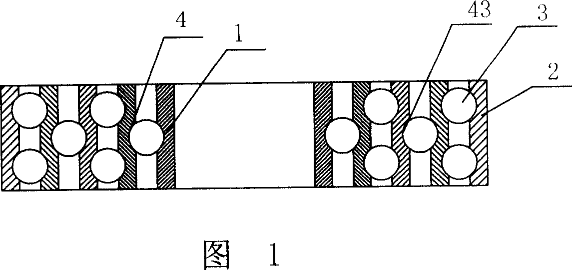
[0013] Embodiment 1: As shown in Figure 1, a high-speed bearing includes an inner ring 1 and an outer ring 2, and three middle rings 4 are coaxially arranged between the inner ring 1 and the outer ring 2, and the inner and outer sides of the middle ring 4 are respectively An annular groove 43 is provided, and four groups of rolling elements 3 are respectively arranged in the inner and outer annular grooves 43 of the three middle rings 4 .
Embodiment 2
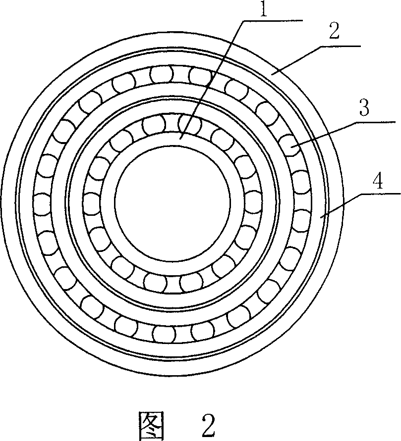
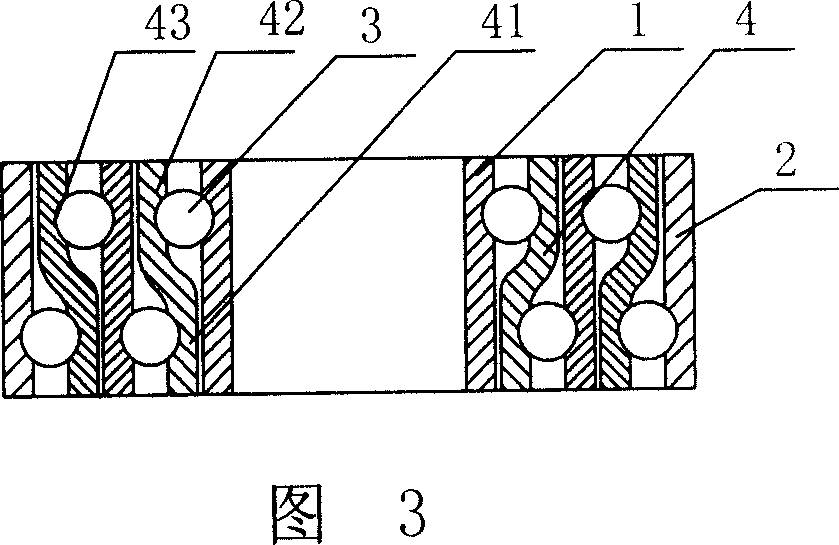
[0014] Embodiment 2: As shown in Figures 2 and 3, a high-speed bearing includes an inner ring 1 and an outer ring 2, and three middle rings 4 and four sets of rolling elements are coaxially arranged between the inner ring 1 and the outer ring 2 3. The middle ring 4 includes a first middle ring cylinder 41 and a second middle ring cylinder 42 which are integrally arranged. The diameters of the first middle ring cylinder 41 and the second middle ring cylinder 42 change in a step shape. The diameter of the ring cylinder 41 is smaller than the diameter of the second middle ring cylinder 42, and the outer surface of the first middle ring cylinder 41 and the inner surface of the second middle ring cylinder 42 are respectively provided with annular recesses that can accommodate the rolling elements 3. Groove 43, four sets of rolling elements 3 are respectively arranged in the annular groove 43 on the outside of the first middle ring cylinder 41 and the inner side of the second middle ...
PUM
 Abstract
Description
Claims
Application Information