Preparation method of PPR plastic permanent magnet cut off valve

A globe valve, plastic technology, applied in the direction of lift valve, valve details, valve device, etc., can solve the problems of increased engineering cost, unable to adjust flow, loose metal inserts, etc., to overcome high manufacturing cost, convenient installation and maintenance, adjustment The effect of flow

Inactive Publication Date: 2007-04-18
钟荷清
View PDF1 Cites 4 Cited by
  • Summary
  • Abstract
  • Description
  • Claims
  • Application Information

AI Technical Summary

Problems solved by technology

[0002] All kinds of traditional stop valves are operated by rods and shafts, and leakage at the dynamic seals of rods and shafts is inevitable; when installing metal stop valves in PPR plastic pipeline projects, it is necessary to change the hot-melt connection into a threaded connection. Special accessories greatly increase the project cost; the existing PPR globe valve, in the process of repeated tightening and loosening of the valve, it is easy to loosen its metal inserts and cause leakage. When replacing the valve, part of the pipeline must be replaced ; The known permanent magnet stop valve technology (ZL 02 2 79055.1) can not adjust the flow rate, which limits its application range. The permanent magnet stop valve mainly designed with metal materials is not easy because the manufacturing cost is higher than the traditional valve. Promoted in civil water supply pipelines

Method used


Image

  • Preparation method of PPR plastic permanent magnet cut off valve
  • Preparation method of PPR plastic permanent magnet cut off valve
  • Preparation method of PPR plastic permanent magnet cut off valve

Examples


Embodiment 1

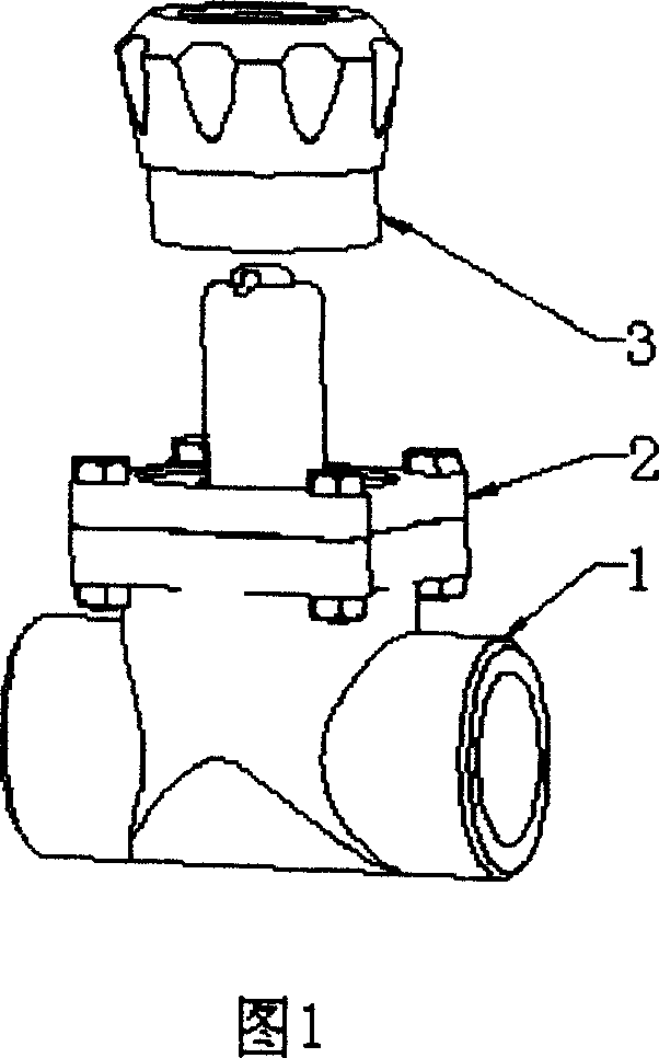
[0012] As shown in Figure 1, the valve seat 1 made of one-time injection of PPR material and the valve cover 2 made of one-time injection of POM material are connected by flanges and bolts, and the operating handle 3 and the internal structure of the valve are still used In the known permanent magnet stop valve (ZL02279055.1) technology, the water inlet and outlet of the valve seat 1 and the PPR pipeline are connected by thermal fusion.

Embodiment 2

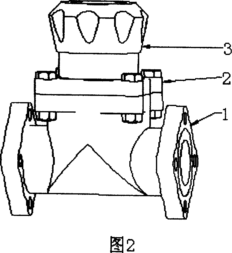
[0014] As shown in Figure 2, the valve seat 1 made of one-time injection of PPR material and the valve cover 2 made of one-time injection of POM material are connected by flanges and bolts, and the operating handle 3 and the internal structure of the valve are still used In the known permanent magnet stop valve (ZL02279055.1) technology, the inlet and outlet of the valve seat 1 and the non-PPR material pipeline are connected by flanges and bolts.

Embodiment 3

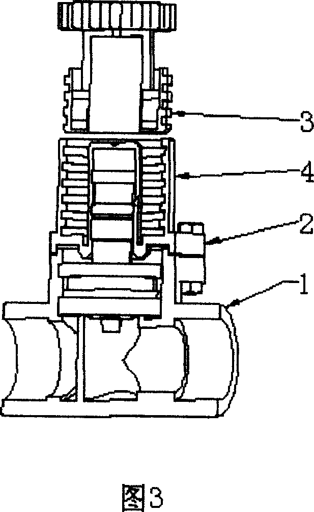
[0016] As shown in Figure 3, the valve seat 1 made of one-time injection of PPR material and the valve cover 2 made of one-time injection of POM material are connected by flanges and bolts. The difference from Figure 1 and Figure 2 is that : Add a peripheral guide sleeve 4 with internal thread on the valve cover 2, add external thread outside the operating handle 3, the operating handle 3 and the peripheral guide sleeve 4 form a threaded connection, and rotate the operating handle 3 forward and reverse to make it permanent The magnet moves up and down and stays at any position, thereby controlling the armature in the valve to stay at different positions, so that the valve can control different flow rates.


PUM


Abstract

A PPR plastics permanent-magnet stop valve comprises a valve seat single-injection moulded of PPR plastics, a valve deck made of high-strength engineering plastics and metal connected with the valve seat via a flange plate and a bolt and an operating handle forming a threaded connection with the outside guide cover on the valve deck.

Description

technical field [0001] The invention relates to the technical field of permanent magnet valves, in particular to a preparation method of a PPR plastic permanent magnet stop valve. Background technique [0002] All kinds of traditional stop valves are operated by rods and shafts, and leakage at the dynamic seals of rods and shafts is inevitable; when installing metal stop valves in PPR plastic pipeline projects, it is necessary to change the hot-melt connection into a threaded connection. Special accessories greatly increase the project cost; the existing PPR globe valve, in the process of repeated tightening and loosening of the valve, it is easy to loosen its metal inserts and cause leakage. When replacing the valve, part of the pipeline must be replaced ; The known permanent magnet stop valve technology (ZL 02 2 79055.1) can not adjust the flow rate, which limits its application range. The permanent magnet stop valve mainly designed with metal mater...

Claims


Application Information

Patent Timeline
Patent Type & Authority Applications(China)
IPC IPC(8): F16K1/00F16K27/00
Inventor 钟荷清
Owner 钟荷清
Why Eureka
Try Eureka