Encoding device, decoding device, and method thereof
A coding device and coding technology, which are applied in code conversion, speech analysis, instruments, etc., can solve the problem of increasing coding delay, and achieve the effect of improving subjective quality.
- Summary
- Abstract
- Description
- Claims
- Application Information
AI Technical Summary
Problems solved by technology
Method used
Image

Examples
Embodiment approach 1
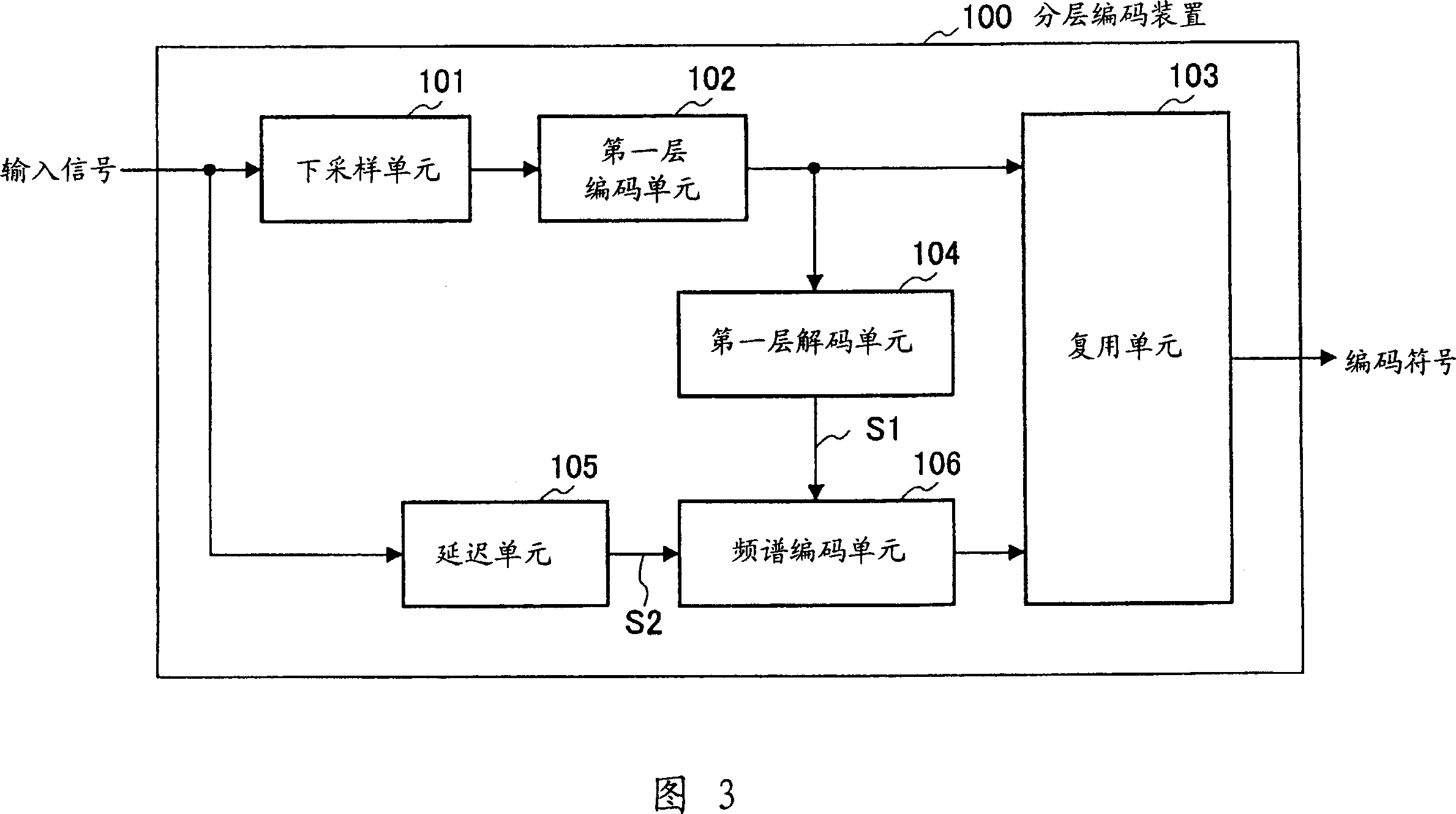
[0055] Fig. 3 is a block diagram showing the main configuration of hierarchical coding apparatus 100 according to Embodiment 1 of the present invention. Here, a case where the coded information has a hierarchical structure consisting of multiple layers, that is, a case where layered coding (scalable coding) is performed, will be described as an example.
[0056] Each part of the layered encoding device 100 performs the following operations according to the input of a signal.
[0057] The down-sampling unit 101 generates a signal with a low sampling rate according to the input signal, and provides it to the first-layer encoding unit 102 . The first layer encoding unit 102 encodes the signal output from the downsampling unit 101 . The encoded symbols obtained by the first layer encoding section 102 are supplied to the multiplexing section 103 and the first layer decoding section 104 . Then, the first-layer decoding unit 104 generates the first-layer decoded signal S1 according...
Embodiment approach 2
[0133] In Embodiment 2 of the present invention, the second spectrum is estimated using the pitch filter having the first spectrum as an internal state, and the characteristics of the pitch filter are encoded.
[0134] The structure of the layered coding apparatus according to this embodiment is the same as that of the layered coding apparatus described in Embodiment 1. Therefore, the difference in structure, that is, spectrum coding section 201 will be described using the block diagram of FIG. 11 . Components that are the same as those in spectrum encoding section 106 (see FIG. 4 ) described in Embodiment 1 are given the same reference numerals, and description thereof will be omitted.
[0135] The internal state setting unit 203 sets the internal state S(k) for the filtering unit 204 using the deformed first spectrum S1'(k) generated by the spectrum deforming unit 112.
[0136] The filtering unit 204 performs filtering based on the internal state S(k) set by the internal sta...
Embodiment approach 3
[0181] Fig. 14 is a block diagram showing the main configuration of a spectrum encoding unit according to Embodiment 3 of the present invention. In FIG. 14 , blocks having the same names and the same numbers as those in FIG. 4 have the same functions, and therefore description thereof will be omitted. In Embodiment 3, the dynamic range of the frequency spectrum is adjusted based on information common to the encoding side and the decoding side. Therefore, there is no need to output coded symbols representing dynamic range coefficients for adjusting the dynamic range of the frequency spectrum. The bit rate can be reduced because there is no need to output coded symbols that will represent dynamic range coefficients that adjust the dynamic range of the frequency spectrum.
[0182] The spectrum coding unit 301 in FIG. 14 has a dynamic range calculation unit 302, a deformation information estimation unit 303, and a deformation unit 304 between the frequency domain transformation u...
PUM
 Abstract
Description
Claims
Application Information
 - R&D
- Intellectual Property
- Life Sciences
- Materials
- Tech Scout
- Unparalleled Data Quality
- Higher Quality Content
- 60% Fewer Hallucinations
Browse by: Latest US Patents, China's latest patents, Technical Efficacy Thesaurus, Application Domain, Technology Topic, Popular Technical Reports.
© 2025 PatSnap. All rights reserved.Legal|Privacy policy|Modern Slavery Act Transparency Statement|Sitemap|About US| Contact US: help@patsnap.com