Slide fastener slider with automatic locking device

An automatic locking and zipper technology, applied in the direction of sliding fastener components, applications, fasteners, etc., can solve the problems of not being able to easily assemble sliders, difficult installation, etc.

Active Publication Date: 2007-04-25
YKK CORP
View PDF2 Cites 20 Cited by
  • Summary
  • Abstract
  • Description
  • Claims
  • Application Information

AI Technical Summary

Problems solved by technology

However, the assembly of the slider is a difficult installation for a single...

Method used


Image

  • Slide fastener slider with automatic locking device
  • Slide fastener slider with automatic locking device
  • Slide fastener slider with automatic locking device

Examples


no. 1 example

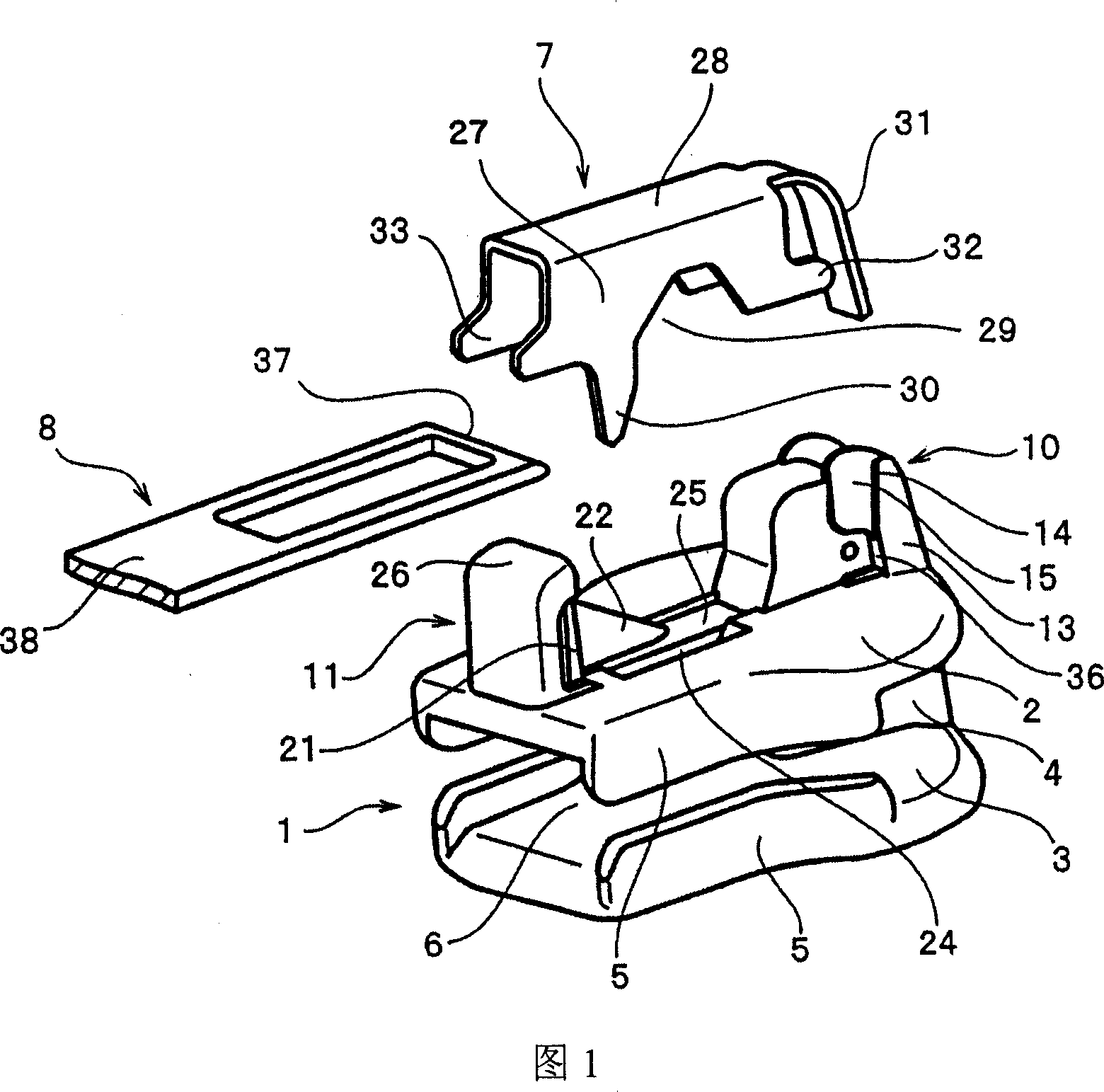
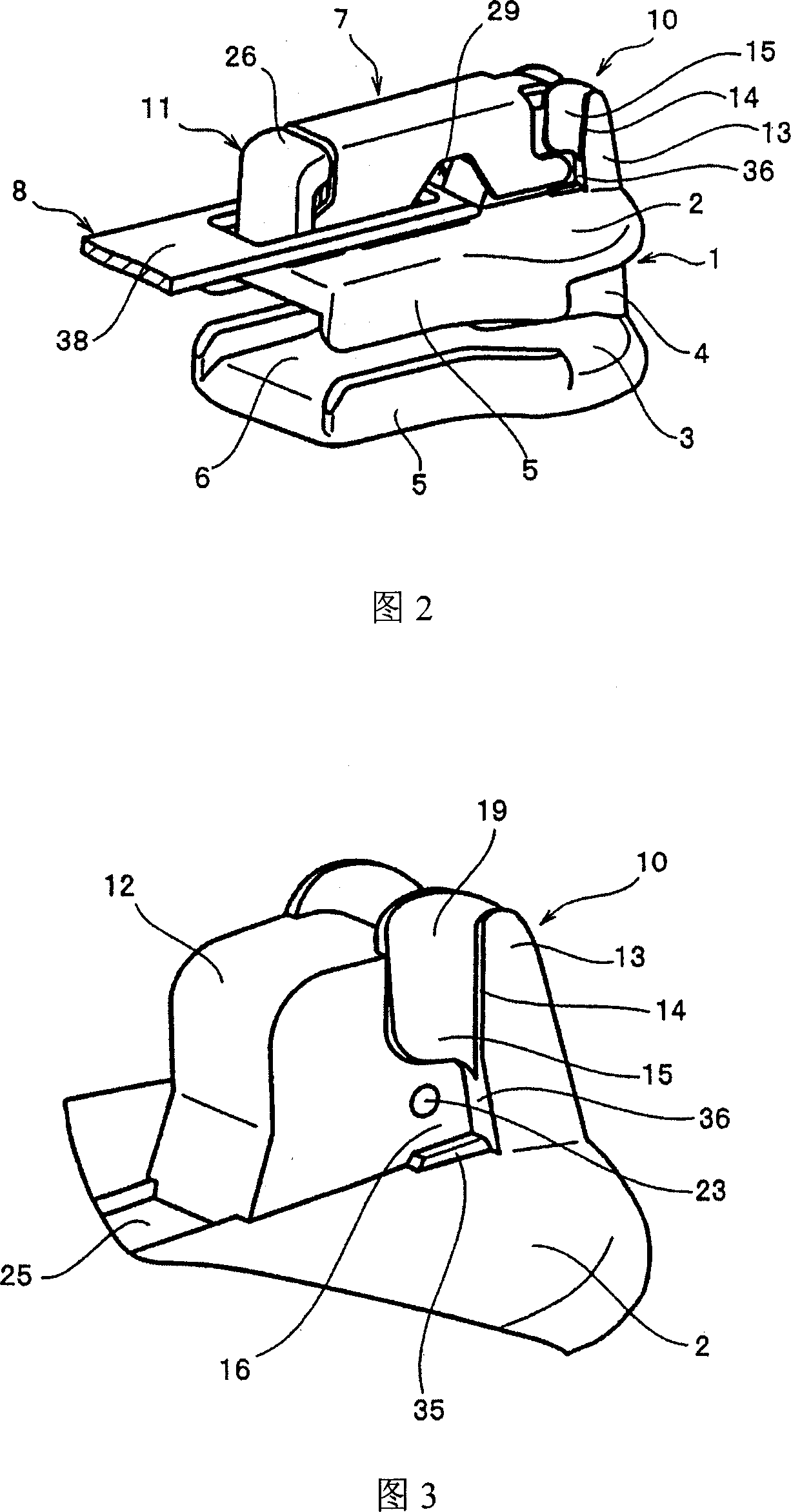
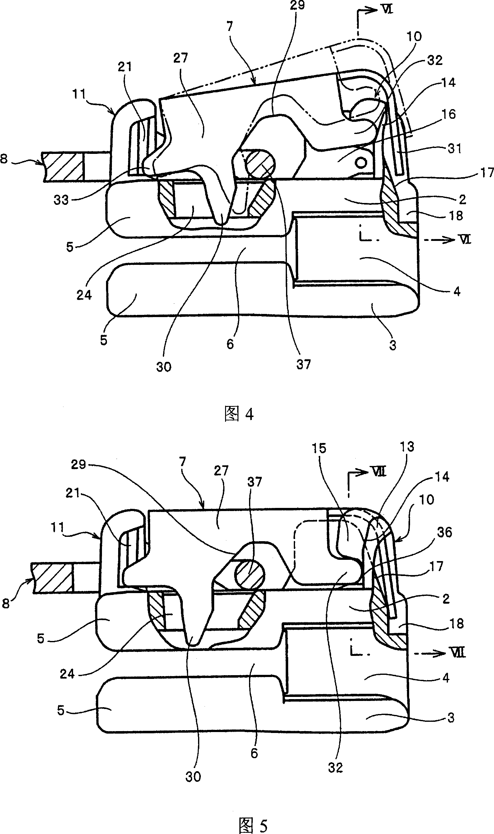
[0045] The sliding zipper slider with automatic locking device according to the first embodiment shown in FIGS. 1 to 7 is preferably configured in such a way that its body 1 is cast by die-casting metal such as zinc alloy or aluminum alloy, and the cover 7 is formed by extruding sheet steel or the like, and tab 8 is cast by die casting metal. The cover 7 may be molded by using a thermoplastic resin such as polyamide, polyacetal, polypropylene or polypropylene terephthalate, and the puller that one prefers to use. A tab can be used as pull tab 8 .

[0046] The slider with automatic stop mechanism is configured by three components: body 1 , cover 7 and pull tab 8 . A locking claw 30 as a locking mechanism is provided on one side surface of the cover 7 so that the locking claw 30 can be inserted between the left and right zipper elements by operating the pull tab 8 . Zipper elements that can be applied to the slider shown in the drawings as an example include zipper elements th...

no. 2 example

[0057] The sliding zipper slider with an automatic locking device according to the second embodiment shown in FIGS. 9 and 10 has the same structure as that of the first embodiment, except that the supporting part is provided at the front attachment post 10. The structure of the relationship between the expansion portion 13 and the hook piece 15 on each of the two sides of the 12 is different.

[0058] The front attachment post 10 erected on the body 1 has a trapezoidal support portion 12 at its center, and expansion portions 13 are provided on both sides of the support portion 12 so as to protrude from the support portion 12 . The hook piece 15 is protruded from a substantially upper half of the expansion portion 13 to the rear mouth side, and the top side of the hook piece 15 is provided with an inwardly inclined slope 19 . A step is provided on the boundary between the expanded portion 13 and the hook piece 15 so that the guide portion 14 for guiding the front engaged portio...


PUM


Abstract

The invention provides a sliding zipper slider with an automatic locking device, comprising: a body (1), a cover (7) and a pull piece (8); arranged in a claw hole (24) in the body (1) The front and rear front and rear attachment posts (10, 11); the cover (7) has a front bonded part (32) at the front side, a rear bonded part (33) at the rear side and an elastic piece at the front end ( 31); the locking pawl (30) is arranged on the rear end of at least one of the openings (29) of the side wall (27); the front attachment post (10) has an extension (13) on its side surface; by Hook sheet (15) is set from the part of the center of the rear end of each extension part (13) from the top, and accommodating part (16) is arranged below the hook sheet (15); Guide part (14) is arranged on extension part (13) ) and the hook piece (15); and the pivot (37) of the pull piece (8) is installed in the opening (29), so that the front engaged part (32) is guided into the receiving part (16) and installed On which is attached the cover (7), through which the user can freely assemble the slider later with his or her desired pull tab.

Description

field of invention [0001] The present invention relates to a slider used in a sliding zipper with an automatic locking device, in particular to a slider for a sliding zipper with an automatic locking device. pull-tab ) can play the locking role of the slider when activated. Background technique [0002] In general, the following sliders for sliding zippers with automatic locking devices are already known as described in US Patent Application No. 2,657,445. In the cover 107 constructed between the cover attachment posts standing between the front and rear positions of the slider body, as shown in the developed view of FIG. The piece 131 is protrudingly provided, and an engagement piece 150 capable of being swingably attached to the front attachment post is provided under proximal portions of the elastic piece 131 . An engagement piece 150 that is swingably attached to the rear attachment post is provided at the other end, that is, at the rear end of the cover 107 . Then, l...

Claims


Application Information

Patent Timeline
IPC IPC(8): A44B19/30
CPCA44B19/306
Inventor 槻庆一岩濑裕一
Owner YKK CORP
Why Eureka
Try Eureka