Spring thrust down clamp of direct tensile test

A tensile test, support technology, applied in the direction of applying stable tension/pressure to test the strength of materials, measuring devices, instruments, etc., can solve the problem of ineffective support, and achieve simple structure, convenient use and easy assembly. Effect

Inactive Publication Date: 2007-04-25
SICHUAN UNIV
View PDF0 Cites 46 Cited by
  • Summary
  • Abstract
  • Description
  • Claims
  • Application Information

AI Technical Summary

Problems solved by technology

During the tensile test, since there is a certain gap between the backing plate 6 and the sample fixing groove of the lower end cap 7, the rigid sleeve 4 cannot effectively support the weight of the sample 8 and the lower end cap 7 during the entire test process. Whe

Method used


Image

  • Spring thrust down clamp of direct tensile test
  • Spring thrust down clamp of direct tensile test
  • Spring thrust down clamp of direct tensile test

Examples


Embodiment 1

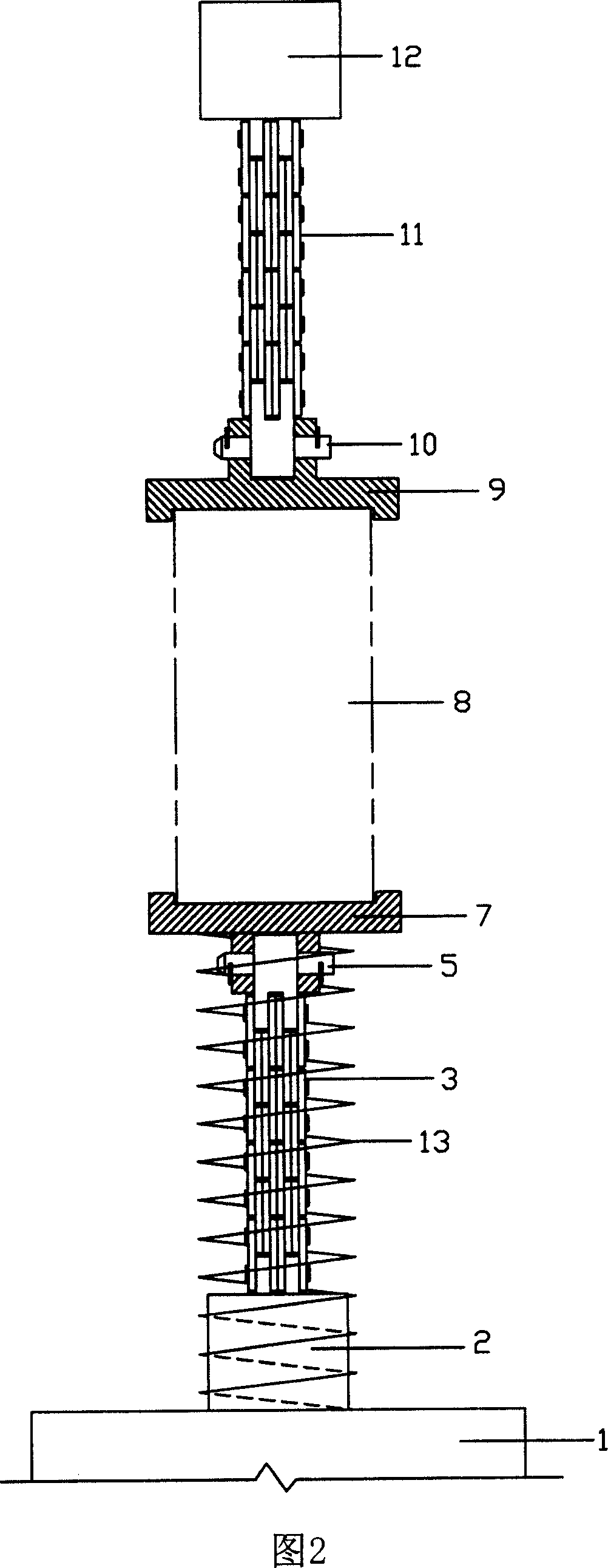
[0018] In this embodiment, the structure of the spring-supported lower fixture for the direct tensile test is shown in Figure 2, including the lower joint 2 connected to the base of the testing machine, the lower end cap 7 for fixing the sample, and the lower end cap for connecting the lower joint and the lower end cap. Chain 3. A supporting member for the sample and the lower end cap damaged by the tensile test. The supporting member is a cylindrical compression coil spring 13, and the free height H of the cylindrical compression coil spring is 0 It is greater than the sum of the height of the lower end cap, the lower chain and the lower joint by 3cm to 6cm, and the initial compression amount (the compression amount when the cylindrical compression coil spring is set) is its free height H 0 15% to 25% of the weight, the maximum load is not less than the sum of the weight of the sample, the lower end cap and the lower chain. The lower end cap 7 is composed of a sample fixing ...

Embodiment 2

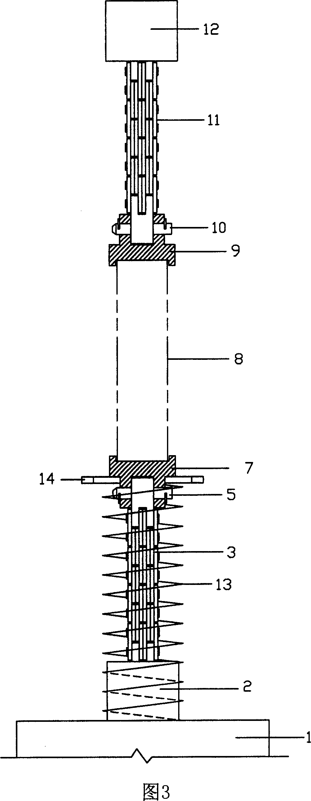
[0022] In this embodiment, the structure of the spring-supported lower clamp for the direct tensile test is shown in Figure 3, including the lower joint 2 connected to the base of the testing machine, the lower end cap 7 for fixing the sample, and the lower end cap for connecting the lower joint and the lower end cap. Chain 3. A supporting member for the sample and the lower end cap damaged by the tensile test. The lower end cap 7 is composed of a sample fixing groove and a connecting section. The supporting member is composed of a cylindrical compression coil spring 13 and a supporting plate 14. The outer diameters of the lower end cap sample fixing groove and the connecting section are smaller than that of the cylindrical compression coil spring. the inside diameter of. The free height H of the cylindrical compression coil spring 13 0 It is greater than the sum of the height of the lower end cap, the lower chain and the lower joint by 3cm to 6cm, and the initial compression...


PUM


Abstract

A spring supporting inferior jig of direct tensile test is disclosed that comprises lower connector which is connected with the tester base, lower end cap of the set sample, lower chain which joins the lower end cap and the lower connector, bracing member which cases the destructed sample in the tensile test and the lower end cap, the lower end cap consists of sample fixing trough and linkage segment, the bracing member is the spiral compression springs; one end of the spiral compression spring is connected or contacted with the sample fixing trough of the lower end cap, the other end of the spiral compression spring is connected or contacted with the tester base, the linkage segment of the lower end cap, the lower chain and the lower connector are cased in the spiral compression spring, one end of the lower chain is connected with the lower end cap, the other end of the lower chain is connected with the lower connector. In the entire test, the sample, the lower end cap and the lower chain are supported by the spiral compression spring to avoid the condition that the sample is suddenly destroyed by the effect of the gravity when the pulling stress reaches the peak, so the stress effect test can be preceded after the peak stress.

Description

technical field [0001] The invention belongs to a fixture used for direct tension test on brittle materials, in particular to a fixture used for fixing samples in direct tension test of rocks. Background technique [0002] Tensile strength is an important mechanical property of brittle materials such as rocks. At present, in the tensile test for directly measuring the tensile strength of rock, the structure of the sample fixing fixture matched with the testing machine is shown in Figure 1, which consists of an upper fixture and a lower fixture. Both the upper clamp and the lower clamp include a joint connected to the tensile testing machine, an end cap for fixing the sample, and a chain connecting the joint and the end cap. The lower fixture also includes a supporting member composed of a rigid sleeve 4 and a backing plate 6 because it is required to bear part of the sample and the lower end cap destroyed by the tensile test. During the tensile test, since there is a certa...

Claims


Application Information

Patent Timeline
IPC IPC(8): G01N3/04G01N3/08
CPCG01N3/08G01N2203/0441
Inventor 徐进刘建锋
Owner SICHUAN UNIV
Why Eureka
Try Eureka