Method for scattered radiation correction of a CT system

A technology of scattered radiation and detector systems, which is applied in the fields of instruments, applications, medical science, etc. for radiological diagnosis, and can solve problems such as defective shooting results.

Inactive Publication Date: 2007-05-02
SIEMENS AG
View PDF1 Cites 16 Cited by
  • Summary
  • Abstract
  • Description
  • Claims
  • Application Information

AI Technical Summary

Problems solved by technology

This is disadvantageous especially in the case of CT cardiac recordings with high t

Method used


Image

  • Method for scattered radiation correction of a CT system
  • Method for scattered radiation correction of a CT system
  • Method for scattered radiation correction of a CT system

Examples


Example Embodiment

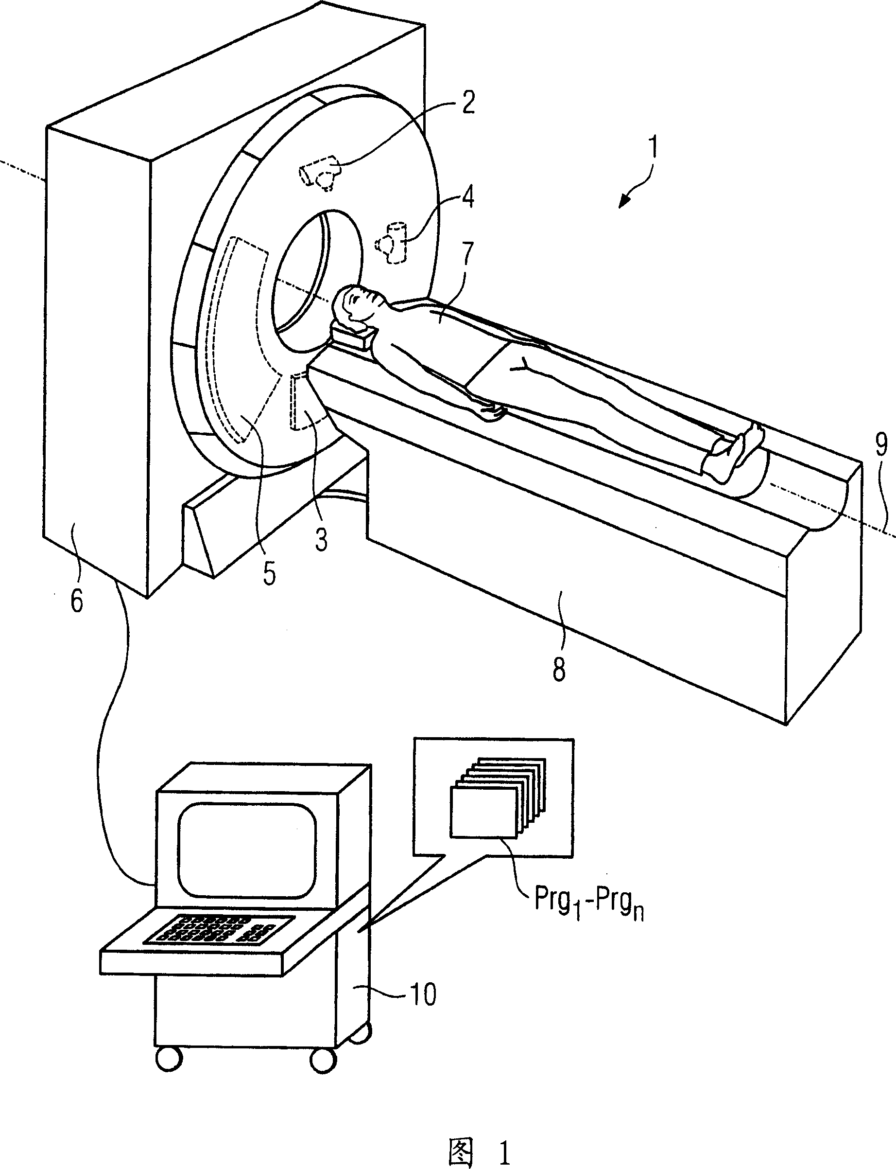
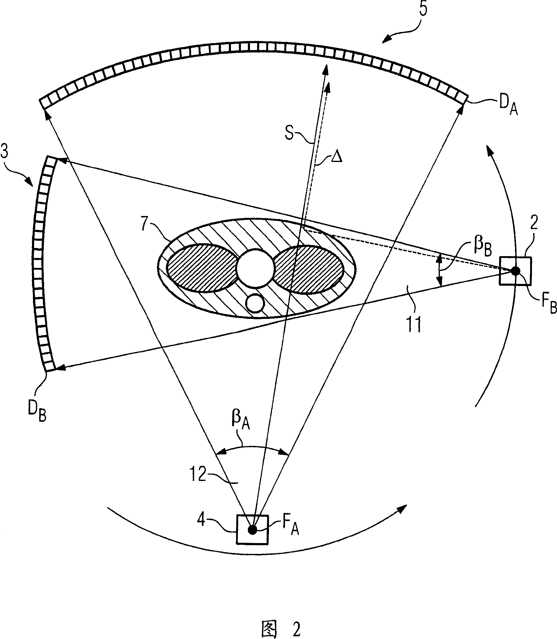
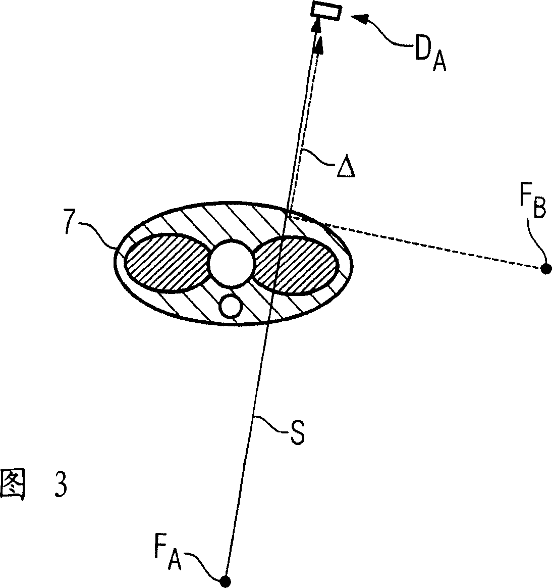
[0023]Figure 1 shows an exemplary computed tomography (CT) system 1 with two focus / detector systems. The focus / detector system includes: a first X-ray tube 2 and an opposite detector 3 The first focus / detector system FDSA, and the second focus / detector system FDSB with the second X-ray tube 4 and the opposite detector 5. The focus / detector systems 2, 3 and 4, 5 are staggered at an angle of 90° in a stent located in the stent housing 6 not explicitly shown here, and move around the system axis 9 during the scanning process, while the patient 7 moves continuously or sequentially through the scanning area. For this purpose, a longitudinally movable patient couch 8 is used, which is controlled by the control and calculation unit 10. The control and calculation unit 10 is also responsible for the control and operation of the stand with two focus / detector systems 2, 3 and 4, 5. In addition, in the control and calculation unit 10, the absorption data obtained by the two focus / detector sy...


PUM


Abstract

The present invention provides a method for scattered radiation correction of a CT system including two simultaneously operated focus/detector systems, arranged angularly offset from one another on a rotatable gantry. In an embodiment of the method, in order to scan an object, the two focus/detector systems arranged angularly offset from one another scan the object by virtue of the fact that they rotate about a system axis of the CT system. A multiplicity of absorption values of individual rays are then determined from the measured attenuations of the radiation of the foci and the measured values are subjected to scattered radiation correction. The positive differences for the direct rays are determined in channelwise fashion from the intensity values of the direct rays and the intensity values of the 'complementary' rays removed by 180 DEG , and this positive difference is subtracted as scattered radiation correction from the intensity value of the direct ray to determine the attenuation values and to thereafter reconstruct CT tomograms or CT volume data.

Description

technical field [0001] The invention relates to a method for radiation correction of a CT system with two focus / detector systems arranged at an angular offset to each other and operating simultaneously on a rotatable support, wherein for scanning an object, the The two angularly offset focal point / detector systems scan (abtasten) the object as follows: they rotate around the system axis of the CT system, and from the measured attenuation of the focal point radiation multiple absorption values ​​for a single ray are determined , and carry out a scattered radiation correction to the measured values ​​in order to reconstruct the CT picture and volume data of the object with the aid of the absorption data obtained. Background technique [0002] A similar method is disclosed, for example, in patent document DE 102 32 429 B3. In this patent document, two focus / detector systems arranged at an angular offset to one another are operated at least temporally alternately, so that in ea...

Claims


Application Information

Patent Timeline
IPC IPC(8): A61B6/03
CPCA61B6/032A61B6/5282A61B6/4014
Inventor 赫伯特·布鲁德马丁·彼得希尔卡
Owner SIEMENS AG
Why Eureka
Try Eureka