Method for controlling dicharge temp of compressor

A technology of compressor exhaust and control method, which is applied in the field of compressors to achieve the effects of improving control logic, rationalizing system operation, and avoiding shutdowns.

Inactive Publication Date: 2007-05-02
LG ELECTRONICS (TIANJIN) APPLIANCES CO LTD
View PDF0 Cites 16 Cited by
  • Summary
  • Abstract
  • Description
  • Claims
  • Application Information

AI Technical Summary

Problems solved by technology

[0005] The technical problem to be solved by the present invention is to provide a compressor discharge temperature control method that can give priority to reducing the discharge port temperature when the discharge port temperature is too high

Method used


Image

  • Method for controlling dicharge temp of compressor
  • Method for controlling dicharge temp of compressor
  • Method for controlling dicharge temp of compressor

Examples


Embodiment Construction

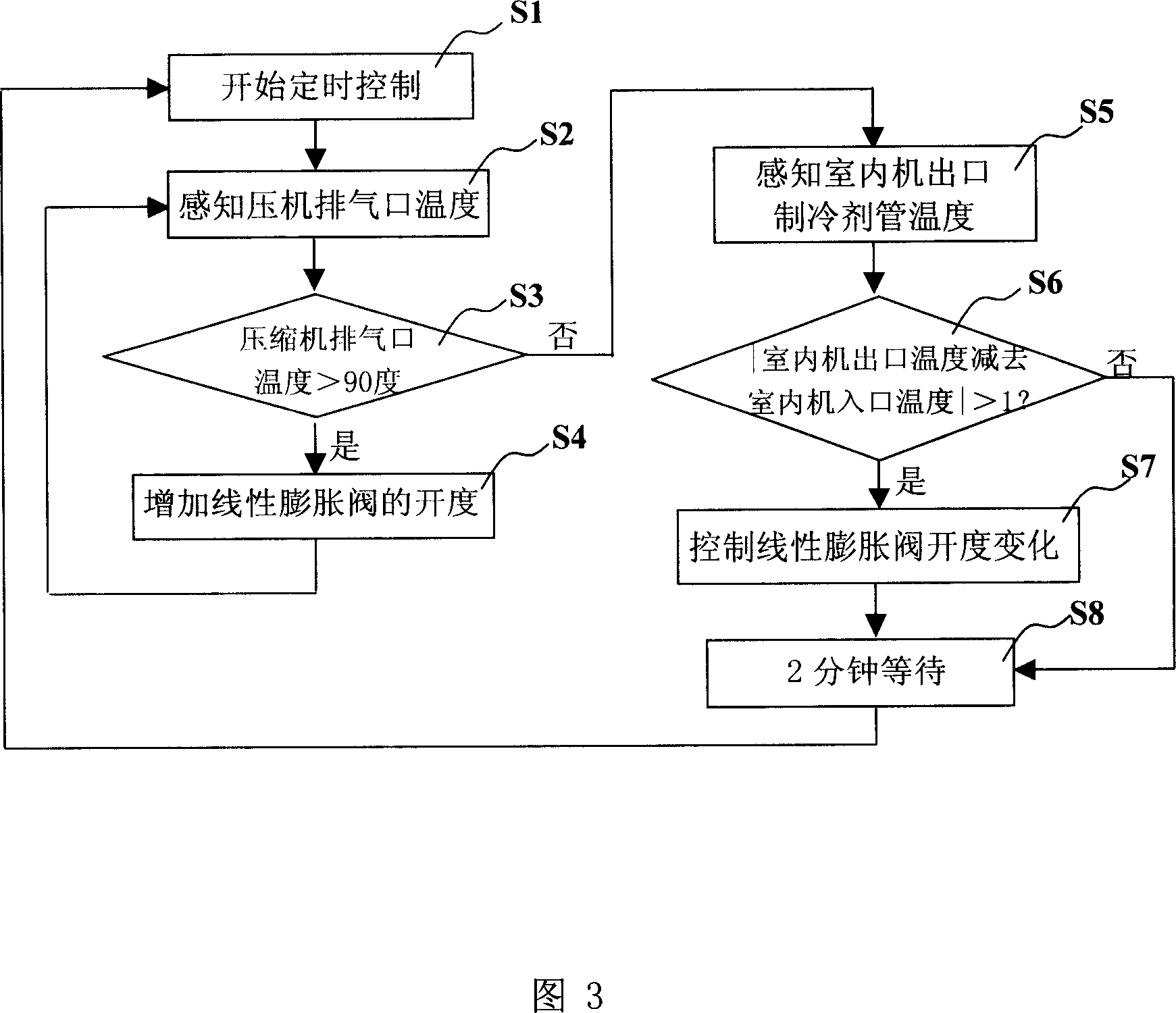
[0020] In the following, the method for controlling the discharge temperature of a compressor according to the present invention will be described in detail in conjunction with the drawings and specific embodiments.

[0021] As shown in Figure 3, the control method of compressor discharge temperature of the present invention comprises the following steps: S1. start timing control; ; S3. judge whether the compressor exhaust port temperature is greater than the set temperature according to the perception result, the set temperature of the present embodiment is 90 degrees, when the judgment result is greater than the set temperature, enter S4, when the judgment result is less than When setting the temperature, enter S5; S4. Increase the opening of the linear expansion valve, the present invention executes 10 openings per minute, and then return to S2 to continue the above control process; S5. Perceive the temperature of the refrigerant pipe at the outlet of the indoor unit , that...


PUM


Abstract

A method for controlling the temp of exhausted air of compressor includes such steps as timing control sensing the temp of air exhaust outlet, judging and controlling according to sensed temp, sensing the temp of refrigerant outlet of indoor set, judging and controlling according to sensed temp, and controlling linear expanding valve.

Description

technical field [0001] The invention relates to a compressor. In particular, it relates to a compressor discharge temperature control method capable of preferentially reducing the discharge port temperature when the discharge port temperature is too high. Background technique [0002] From the perspective of the external structure, the compressor can be regarded as composed of the main body of the compressor and the liquid storage tank. The refrigerant completes the compression process in the main body of the compressor, and the liquid storage tank plays the role of storing and filtering the refrigerant to be compressed. As shown in FIG. 1 , the copper pipe 2 , the filter screen 3 , the liquid storage tank fixing device 4 , the copper pipe 5 and the liquid storage tank shell 6 constitute the basic structure of the liquid storage tank. The liquid storage tank sucks the refrigerant through the suction port 1, and discharges it from the copper pipe 5 after being filtered by t...

Claims


Application Information

Patent Timeline
Patent Type & Authority Applications(China)
IPC IPC(8): F04C28/00
Inventor 黄波
Owner LG ELECTRONICS (TIANJIN) APPLIANCES CO LTD
Why Eureka
Try Eureka