Defrost control method of air conditioner

A control method and technology for air conditioners, applied in defrosting, heating and ventilation control systems, heating methods, etc., can solve the problems of air conditioners reducing heating operation rate and affecting users' use.

Inactive Publication Date: 2007-05-02
LG ELECTRONICS (TIANJIN) APPLIANCES CO LTD
View PDF0 Cites 8 Cited by
  • Summary
  • Abstract
  • Description
  • Claims
  • Application Information

AI Technical Summary

Problems solved by technology

But, there is following problem in this air conditioner of prior art: the defrosting control method that adopts at present is all based on the temperature difference ΔT between the maximum temperature of the indoor refrigerant pipe and the current temperature of the indoor refrigerant pipe. MAX As a benchmark to judge whether defrosting is required, when ΔT MAX = 0°C, the defrosting operation starts, but at this time, the icing on the surface of the condenser 2 in the outdoor unit may not reach the thickness required for defrosting, thus causing the air conditioner to reduce the heating operation rate due to excessive shutdowns and Issues affecting users

Method used


Image

  • Defrost control method of air conditioner
  • Defrost control method of air conditioner

Examples


Embodiment Construction

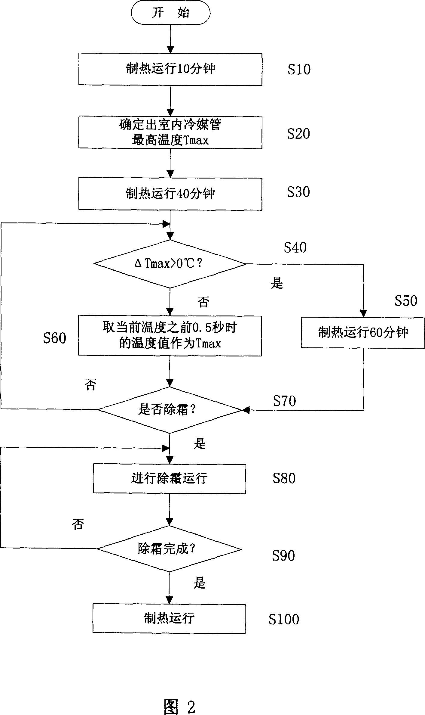
[0009] As shown in Figure 2, the defrosting control method of the air conditioner provided by the present invention includes starting to detect the temperature of the indoor refrigerant pipe after 10 minutes of heating operation and determining the maximum temperature T of the indoor refrigerant pipe. MAX S10, S20 stage; judge the maximum temperature T of the indoor refrigerant pipe every 4 minutes after heating operation for 40 minutes MAX The temperature difference ΔT between the current temperature of the indoor refrigerant pipe MAX Whether it is greater than the S30 and S40 stages of 0°C; if the judgment result of the S40 stage is the temperature difference ΔT MAX If the temperature is greater than 0°C, continue heating operation to the S50 stage for 60 minutes; if the judgment result of the S40 stage is the temperature difference ΔT MAX If it is less than 0°C, take the temperature value 0.5 seconds before the current temperature as T MAX S60 stage; S70 stage for judging...


PUM


Abstract

A method for controlling the defrosting of air-conditioner includes detecting temperature of refrigerant tube and confirming highest temperature TMAX after 10 minutes of heating operation, judging whether temperature difference TMAX between highest temperature TMAX and current temperature is over 0deg.c or not at each 4 minutes interval after 40 minutes heating operation and making said heating operation continuously be 60 minutes if it is or otherwise applying temperature being detected out at time of 0.5 second before current temperature as TMAX then judging whether defrosting should be carried out or not.

Description

technical field [0001] The invention relates to an air conditioner, in particular to a defrosting control method for the air conditioner. Background technique [0002] An air conditioner is a device that makes its internal refrigerant undergo a refrigeration or heating cycle consisting of a compression process, condensation process, expansion process, and evaporation process. Figure 1 is a schematic diagram of the composition of an air conditioner in the prior art. As shown in FIG. 1 , this prior art air conditioner mainly includes a compressor 1 arranged in the outdoor unit, a condenser 2, an expansion valve 3 and an evaporator 4 arranged in the indoor unit. When the air conditioner is in the refrigeration cycle, the refrigerant compressed by the compressor 1 and turned into a high-temperature and high-pressure state first flows to the condenser 2 through the four-way valve 5. In the condenser 2, the refrigerant will dissipate heat to the outside and then flow through the ...

Claims


Application Information

Patent Timeline
Patent Type & Authority Applications(China)
IPC IPC(8): F24F11/00F25D21/06
Inventor 汤菊荣
Owner LG ELECTRONICS (TIANJIN) APPLIANCES CO LTD
Why Eureka
Try Eureka