Method and device for dissolving partial overload in air conditioner

An air-conditioning and partial technology, which is applied in the field of eliminating local overload in air-conditioning, can solve problems such as over-cooling, cooling capacity drop, and users feel cold, and achieve the effect of rapid cooling and increased cooling capacity

Inactive Publication Date: 2007-05-02
LG ELECTRONICS INC
View PDF0 Cites 1 Cited by
  • Summary
  • Abstract
  • Description
  • Claims
  • Application Information

AI Technical Summary

Problems solved by technology

[0012] In this case, if the air conditioner operates at the room temperature detected by each indoor unit, the cooling capacity of the indoor unit installed in a room with an increased cooling load decreases, while the cooling capacity of the indoor unit installed in a room with a constant cooling load decreases. Increased cooling capacity resulting in overcooling of the room, making the user likely to feel cold

Method used


Image

  • Method and device for dissolving partial overload in air conditioner
  • Method and device for dissolving partial overload in air conditioner
  • Method and device for dissolving partial overload in air conditioner

Examples


Embodiment Construction

[0028] The specific examples shown herein are by way of illustration only, to illustrate the description of the embodiments of the invention, and to provide what are believed to be most useful and to facilitate understanding of the principles and conceptual aspects of the invention. Therefore, only the description necessary for the understanding of the basic principles of the present invention is shown, and no attempt is made to show the structural details of the present invention in a more detailed manner, and those skilled in the art can understand the present invention by studying the following description with reference to the accompanying drawings How this can be implemented in practice can be done in a variety of ways.

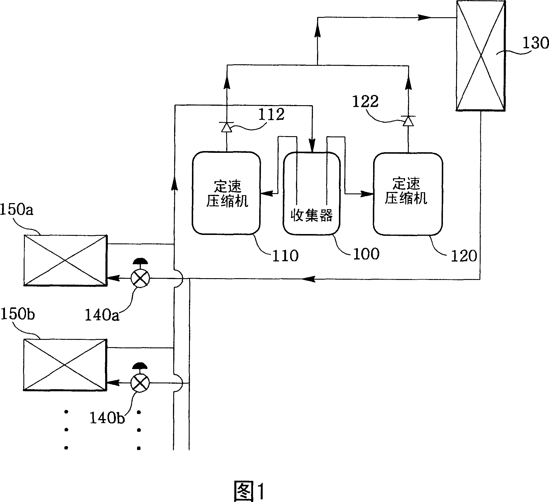
[0029] FIG. 1 is a schematic view showing the structure of a multiple air conditioner adopting a method for eliminating local overload according to the present invention. Here, the reference numeral "100" represents a collector for supplying low-temperat...


PUM


Abstract

A method and device for removing a partial overload in an air conditioner, includes determining whether a plurality of indoor units provided in the air conditioner includes at least one indoor unit operating in an overload state; and performing a partial overload operation to increase the amount of a refrigerant introduced into a corresponding evaporator of the at least one indoor unit when the at least one indoor unit is operating in the overload state.

Description

technical field [0001] The invention relates to a method and a device for eliminating local overloads in an air conditioner. Background technique [0002] Normally, an air conditioner draws hot air from the room in its refrigeration cycle and exchanges heat in the evaporator. The air conditioner then exhausts the cool air created by the heat exchange into the room. The air conditioner repeats the above process to cool the room. [0003] Typically, the refrigeration cycle system includes a closed loop having a compressor, a condenser, an expansion device and an evaporator. [0004] The compressor compresses a low-temperature, low-pressure gaseous refrigerant and converts it into a high-temperature, high-pressure gaseous refrigerant. The high-temperature and high-pressure gaseous refrigerant converted by the compressor is condensed in the condenser, and then converted into a high-temperature and high-pressure liquid refrigerant. [0005] The high-temperature and high-press...

Claims


Application Information

Patent Timeline
Patent Type & Authority Applications(China)
IPC IPC(8): F24F11/00
CPCF25B5/02F25B49/022F25B2700/2104F25B2400/0751F24F11/0086F24F11/0012F24F11/30F24F2110/10F24F11/84F24F11/61F24F11/86F25B1/00F25B49/00
Inventor 朴正宅宋灿豪沈在勋
Owner LG ELECTRONICS INC
Why Eureka
Try Eureka