

Blocking for rotational pendulum body
A supporting device and a pendulum technology, which is applied in the field of rotating pendulum supporting devices, can solve problems such as unstable position, turning deviation, easy turning and shifting, etc., and achieve the effect of convenient and safe use and prevention of lateral movement
- Summary
- Abstract
- Description
- Claims
- Application Information
AI Technical Summary
Problems solved by technology
Method used
Image

Examples
Embodiment Construction
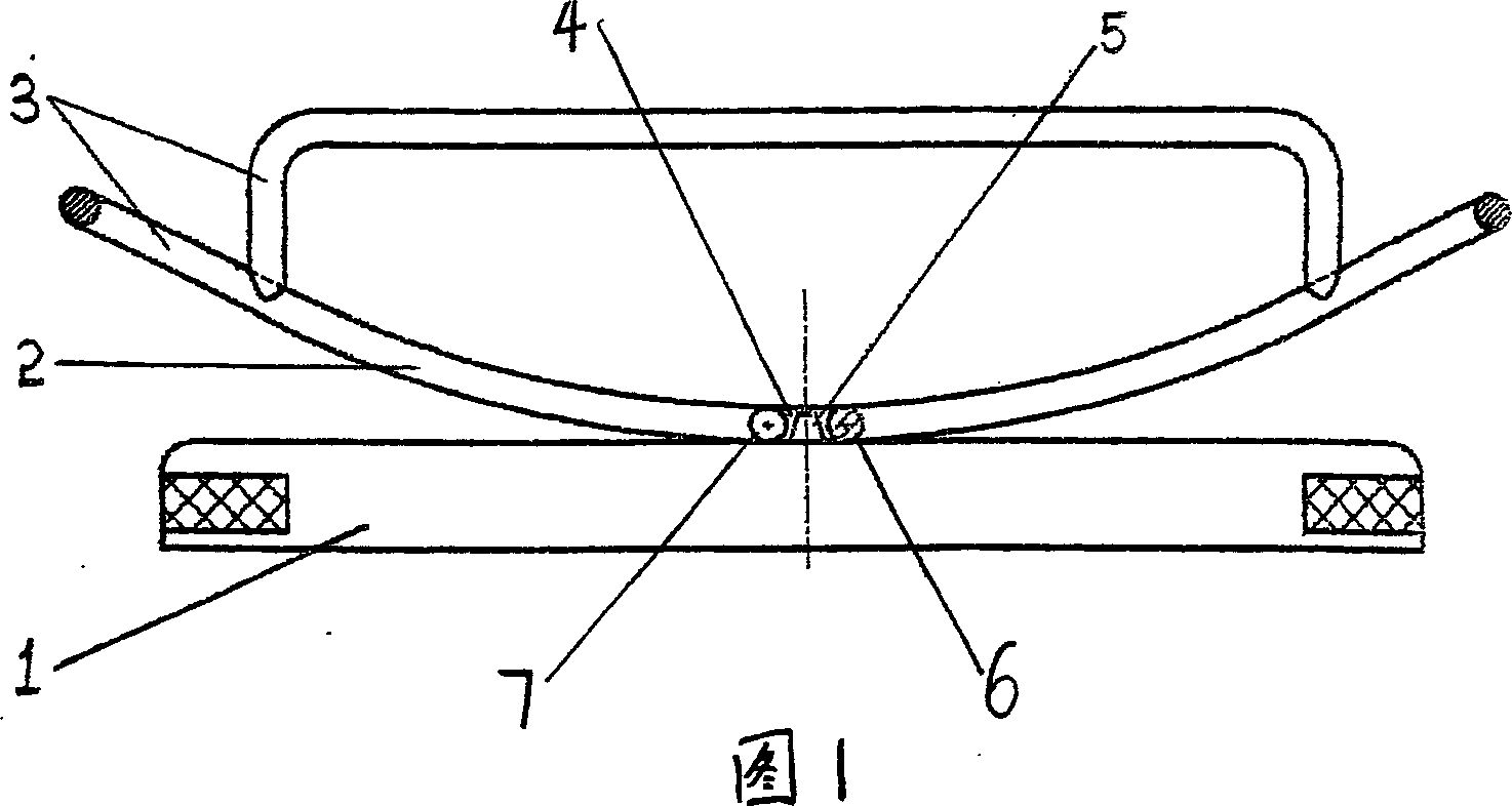
[0022] The technical solution of the present invention includes a base 1, which is characterized in that: the base is provided with a cradle 3 having a pair of parallel curved rockers 2, and the bottom of the cradle 3 is symmetrically provided with at least a pair of positioning slots 4 , the base is correspondingly provided with a protruding pin 5 that can be inserted into the slot 4 to keep the cradle 3 swinging in situ.
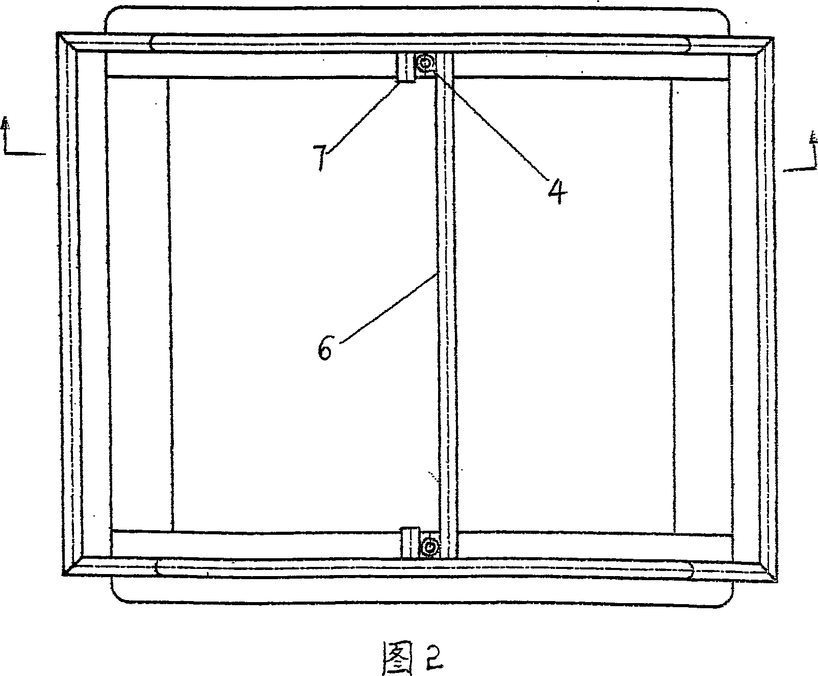
[0023] In order to prevent the longitudinal movement of the rocker, in Example 1 of the present invention, the bottom of the cradle is provided with connecting rods 6 connected to the two inner sides of the rocker through two ends, and at the same time, in order to prevent the lateral movement of the rocker, two ends are respectively provided with a The root is connected to the positioning pin 7 on the inner side of the rocking bar, so that the slot 4 is formed between the two ends of the connecting rod and the positioning pin 7, and the base is correspondi...
PUM
 Abstract
Description
Claims
Application Information