Float push-pull type fiber filter

A fiber filter and filter technology, which is applied in the direction of gravity filter, loose filter material filter, filtration and separation, etc., can solve the problems of adding valves and increasing equipment operation steps, so as to reduce operation steps, ensure filtration effect and Cleaning effect, buoyancy reduction effect

Inactive Publication Date: 2007-05-16
SHANGHAI FANQING ENVIRONMENT ENG
View PDF1 Cites 3 Cited by
  • Summary
  • Abstract
  • Description
  • Claims
  • Application Information

AI Technical Summary

Problems solved by technology

[0003] The main disadvantage is that it needs to add valves for filling and draining or filling and exhausting, and increase the operation steps in the process of using the equipment

Method used


Image

  • Float push-pull type fiber filter
  • Float push-pull type fiber filter
  • Float push-pull type fiber filter

Examples


Embodiment Construction

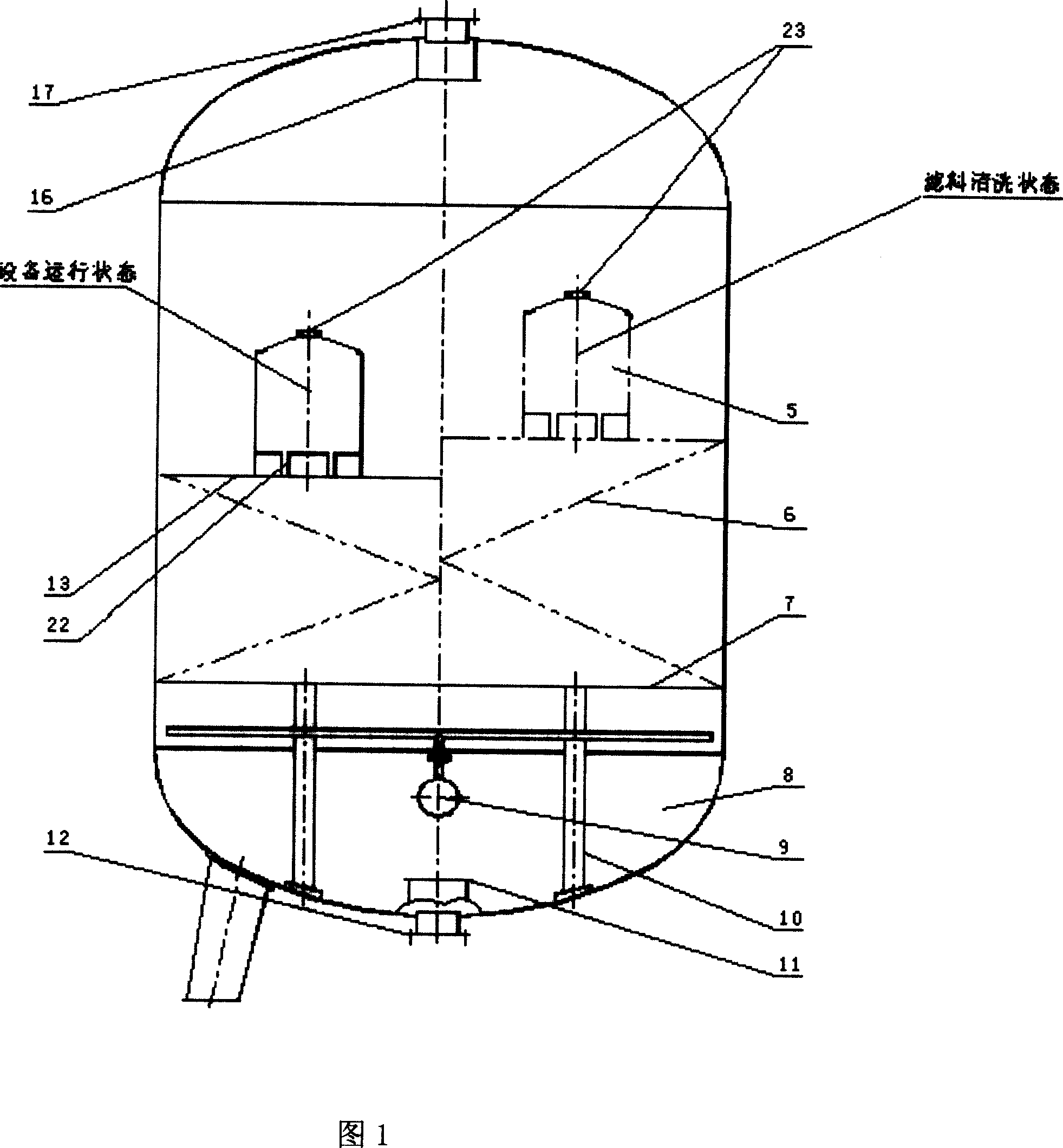
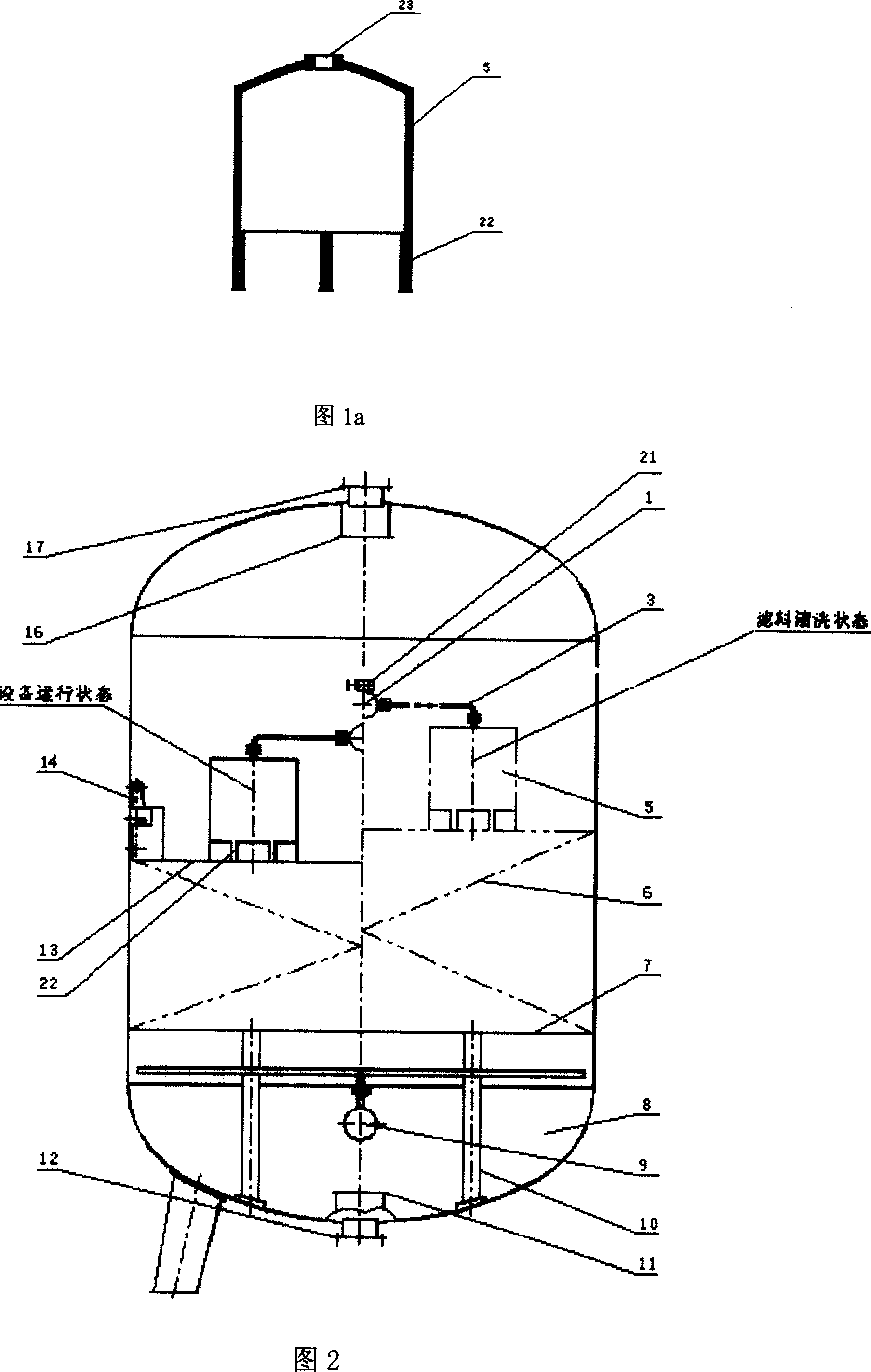
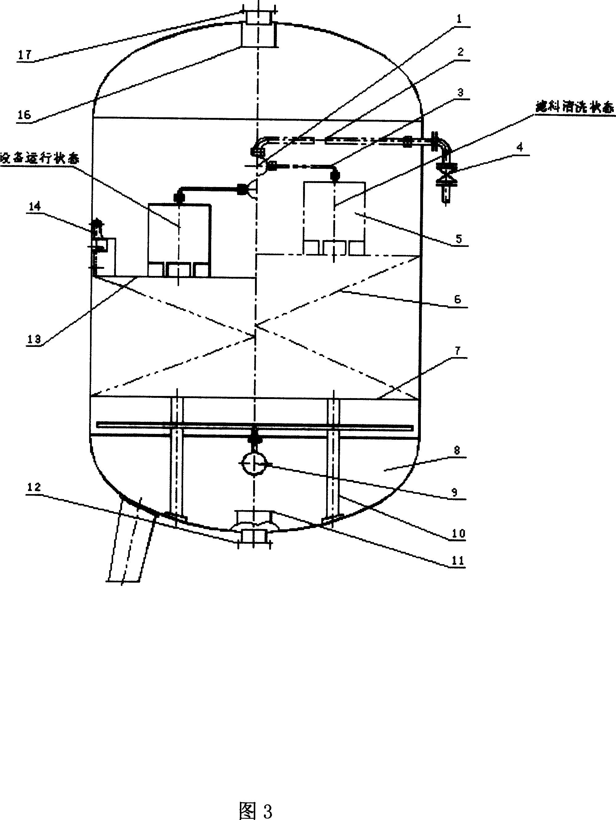
[0019] Referring to Fig. 1 and Fig. 1a, the fiber filter of the present invention mainly includes a housing 8, a fixed porous support device 7 installed in the housing 8, and a movable porous support device 13, which is fixed on the fixed porous support device 7 and the movable porous support device. The fiber bundle filter element 6 on 13, and the water inlet 17 and water outlet 12 installed on the housing 8, the upper water distribution device 16 and the lower water distribution device 11 installed on the housing 8, and the gas distribution device installed on the lower part of the housing 8 9; the fixed porous support device 7 is supported on the lower head through the support member 10; the movable porous support device 13 is arranged above the fixed support porous plate 7, the water inlet 17 is on the upper part of the housing 8, and the water outlet 12 is on the upper part of the housing 8 Bottom; the gas collecting hood 5 is set on the movable porous support device 13, t...


PUM

PropertyMeasurementUnit
diameteraaaaaaaaaa
diameteraaaaaaaaaa

Abstract

The invention relates to a fiber filter, which comprises a frame, fixed support porous device inside the frame and movable porous support, the filter frame fixed on the porous device and movable porous support, and the water inlet and outlet on the frame, wherein the support has at least one downward gas collecting frame; when in washing, the collecting frame can collect the air from the lower part of filter used to wash the filter material; float force of the gas collecting frame full with air can eliminate the gravities of movable porous support and gas collecting frame, or generate more drawing force, to loose the fiber beam; in filter process, the air in gas collecting frame can be discharged, to use the gravities of support and itself and the waterflow to compress the filter beam. The invention can confirm the filter effect and reduce the valve number.

Description

technical field [0001] The invention relates to an improvement of a fiber filter or a fiber filter tank, in particular to a density adjustment control scheme of a fiber bundle filter layer. Background technique [0002] Application No. 98201424.4 discloses a fiber bundle filter solution. The filter is mainly composed of a housing, a movable porous plate, a fixed porous plate, and a fiber bundle. The lower porous plate is fixed on the housing, and the upper porous plate can move up and down. The movable porous plate, in order to make the movable porous plate generate downward pressure when filtering and produce upward pulling force when cleaning, a number of boxes are arranged on the movable porous plate, and the boxes can be drained and filled with water or inflated and Exhaust causes it to generate upward buoyancy and downward pressure. [0003] The main disadvantage is that it needs to add valves for filling and draining or filling and exhausting, and it also increases th...

Claims


Application Information

Patent Timeline
Patent Type & Authority Applications(China)
IPC IPC(8): B01D24/00
Inventor 刘澄清刘凡清姜学敏
Owner SHANGHAI FANQING ENVIRONMENT ENG
Why Eureka
Try Eureka