

Melting and pulling method for manufacturing optical tweezers of parabolic microstructure single fiber
A parabolic and manufacturing method technology, applied in the field of optical fibers, can solve the problems of long processing time, complex steps, high processing environment requirements, and achieve the effects of low cost, simple equipment and simple structure
- Summary
- Abstract
- Description
- Claims
- Application Information
AI Technical Summary
Problems solved by technology
Method used
Image

Examples
Embodiment 1
[0042] Example 1: Fabrication of single-fiber optical tweezers with parabolic microstructure.
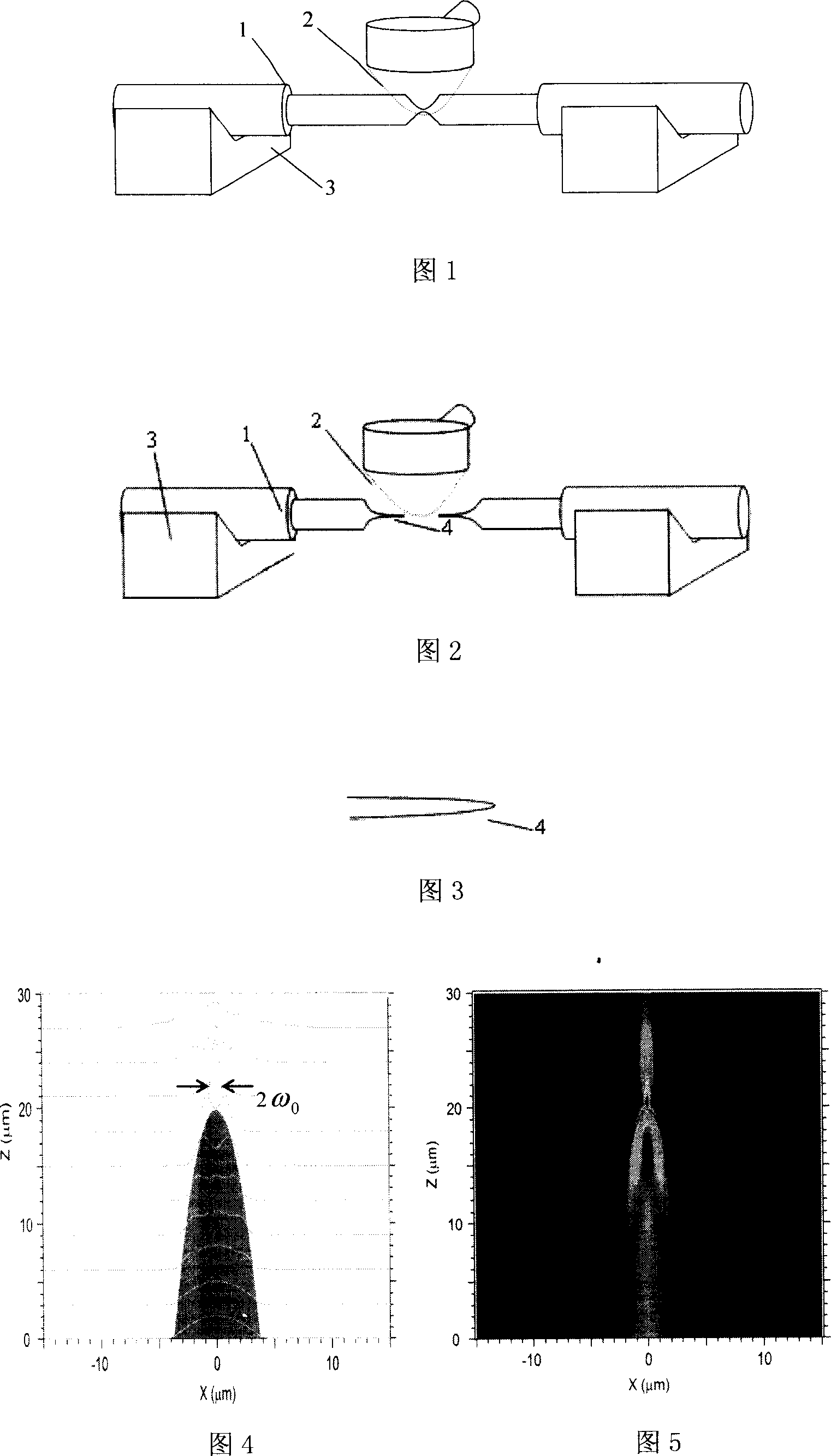
[0043] Combined with Figure 1-3, the specific production steps are:
[0044] 1. Take a section of optical fiber, use optical fiber strippers to strip the coating layer of the optical fiber for 30mm in the middle, and clean the optical fiber cladding with a mixture of alcohol and ether;
[0045] 2. Fix the optical fiber in the movable V-shaped groove, use the electrode to heat the optical fiber in the horizontal state through discharge, the discharge current is selected as 20mA, and control the V-shaped groove to stretch the optical fiber at a speed of 25μm / s while heating. The partially softened part of the optical fiber is gradually thinned, and when the thinnest part of the optical fiber reaches 30 μm, the electrode discharge is stopped;
[0046] 3. Reheat the thinned part in the middle with a hydrogen-oxygen flame, and quickly stretch the fiber at a speed of 2cm / s. When the fibe...
Embodiment 2
[0049]Example 2: Fabrication of single-fiber optical tweezers with parabolic microstructure.
[0050] Combined with Figure 1-3, the specific production steps are:
[0051] 1. Take a section of optical fiber, use optical fiber strippers to strip the coating layer of the optical fiber for 35mm in the middle, and clean the optical fiber cladding with a mixture of alcohol and ether;
[0052] 2. Fix the optical fiber in the movable V-shaped groove, use the electrode to heat the optical fiber in the horizontal state through discharge, the discharge current is selected as 20mA, and control the V-shaped groove to stretch the optical fiber at a speed of 25μm / s while heating. The partially softened part of the optical fiber is gradually thinned, and when the thinnest part of the optical fiber reaches 25 μm, the electrode discharge is stopped;
[0053] 3. Reheat the thinned part in the middle with a hydrogen-oxygen flame, and quickly stretch the fiber at a speed of 2cm / s. When the fiber...
Embodiment 3
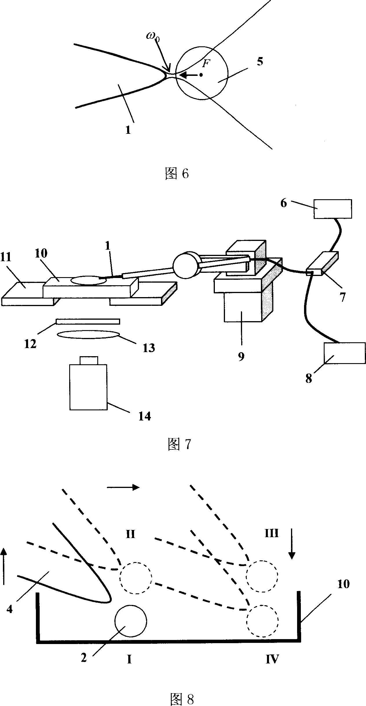
[0055] Embodiment 3: Using a parabolic microstructure single-fiber optical tweezers to realize the transportation of tiny objects.
[0056] Referring to FIG. 7 , the light source 6 uses a laser with a wavelength of λ=980nm. The light emitted by the light source 6 is divided into two beams after passing through a fiber coupler 7 with a splitting ratio of 95:5, one of which is used for power detection 8, and the other beam is transmitted to the parabolic microstructure single-fiber optical tweezers 4 through the optical fiber 1 . After the parabolic microstructure single optical fiber optical tweezers 4 is protected by a steel pipe, it is installed on a mechanical adjustment frame 9 capable of three-dimensional translation and one-dimensional rotation, through which the insertion position and insertion position of the optical fiber in the sample cell 10 can be adjusted. depth and insertion angle. The sample pool 10 is placed on the stage 11 of an inverted biological microscope...
PUM
| Property | Measurement | Unit |
|---|---|---|
| refractive index | aaaaa | aaaaa |
| refractive index | aaaaa | aaaaa |
Abstract
Description
Claims
Application Information