

Disk brake with a spring arrangement
A disc brake, spring device technology, applied in the direction of brake type, brake components, mechanical equipment, etc., can solve problems such as disadvantages
- Summary
- Abstract
- Description
- Claims
- Application Information
AI Technical Summary
Problems solved by technology
Method used
Image

Examples
Embodiment Construction
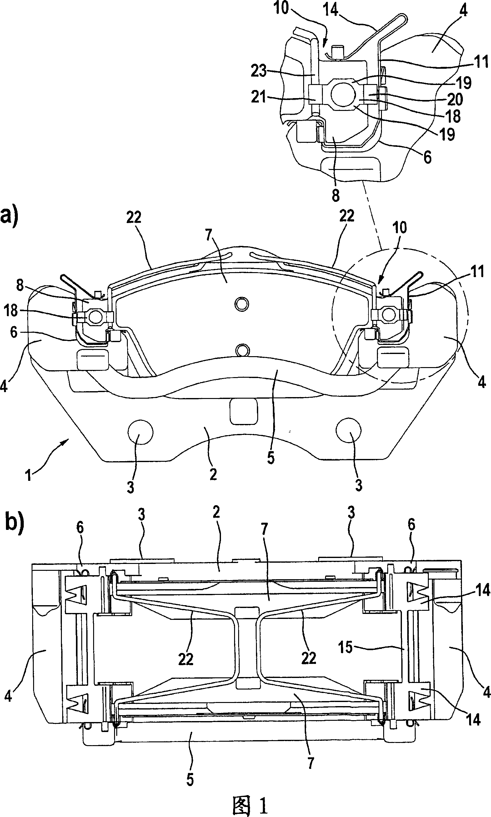
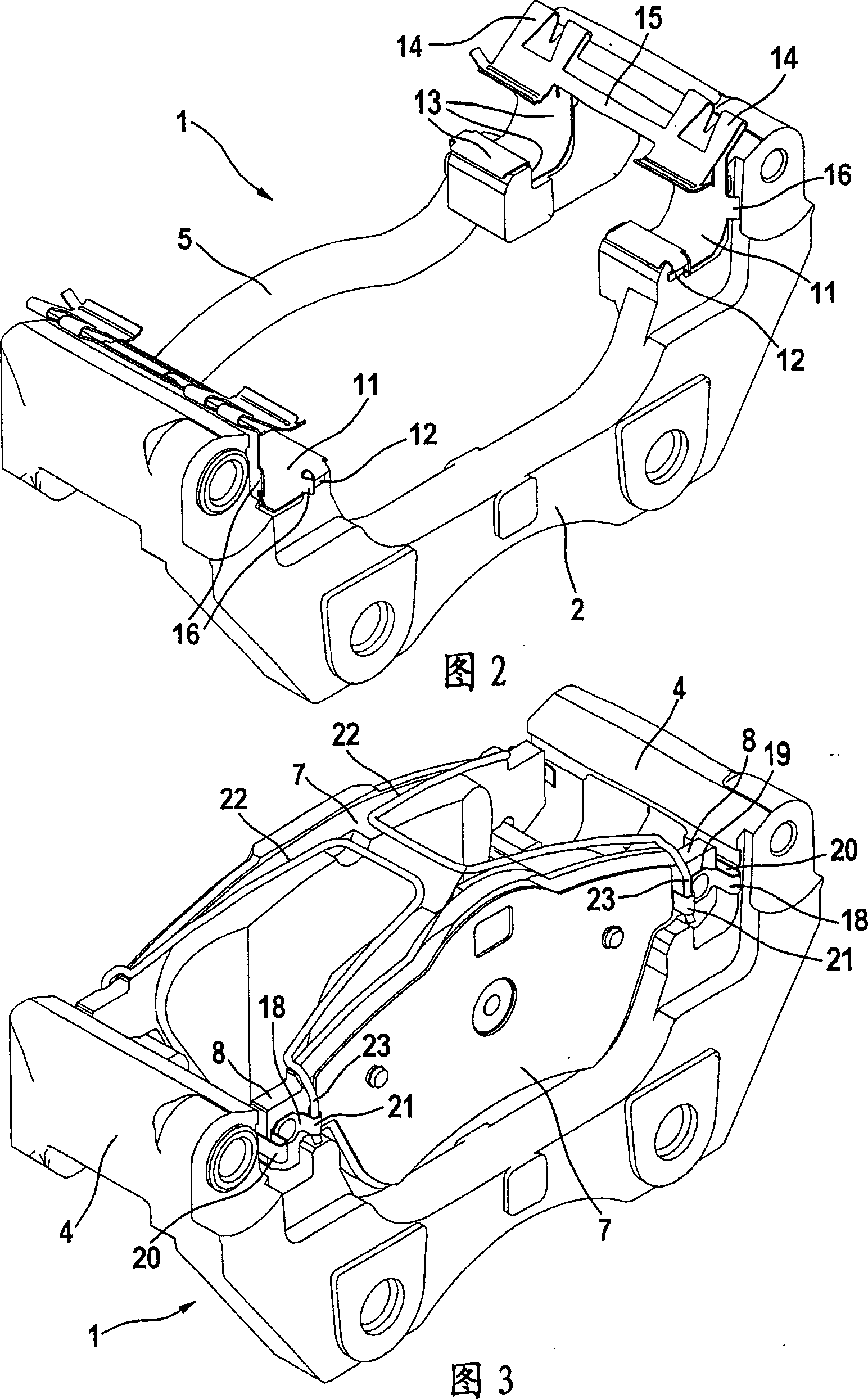
[0015] The brake carrier 1 shown in the figure is a component of a floating-caliper disc brake, as is usually used in motor vehicle braking systems. The brake carrier 1 cooperates here with an associated, but not shown, floating caliper, which is supported axially displaceably on the brake carrier 1 . The brake carrier 1 comprises a base section 2 with fastening holes 3 , via which holes the brake carrier can be mounted in a position-stationary manner or fixedly relative to the vehicle. Attached to the base section 2 is an axially extending support arm 4 which protrudes axially beyond the associated brake disk. To increase the rigidity of the brake carrier, the end of the carrier arm 4 opposite the base section 2 is connected to the web 5 . Formed on the carrier arm 4 is a guide section 6 for receiving a brake shoe 7 which is itself arranged displaceably on the brake carrier 1 . In the guide section 6, each brake shoe 7 is axially movably guided and tangentially supported by...
PUM
 Abstract
Description
Claims
Application Information