
Method and device for examining logic control chip of main control panel

A logic control and chip detection technology, applied in the field of network communication, can solve problems such as the paralysis of the logic control chip system, and achieve the effect of preventing abnormality

Inactive Publication Date: 2007-05-23
HUAWEI TECH CO LTD
View PDF0 Cites 0 Cited by
  • Summary
  • Abstract
  • Description
  • Claims
  • Application Information

AI Technical Summary

Problems solved by technology

[0006] In order to solve the problem that the system is paralyzed due to lack of detection for the logic control chip in the existing active-standby switching scheme, the present invention provides a method and device for detecting the logic control chip of the main control board

Method used


Image

  • Method and device for examining logic control chip of main control panel
  • Method and device for examining logic control chip of main control panel
  • Method and device for examining logic control chip of main control panel

Examples


Embodiment 1

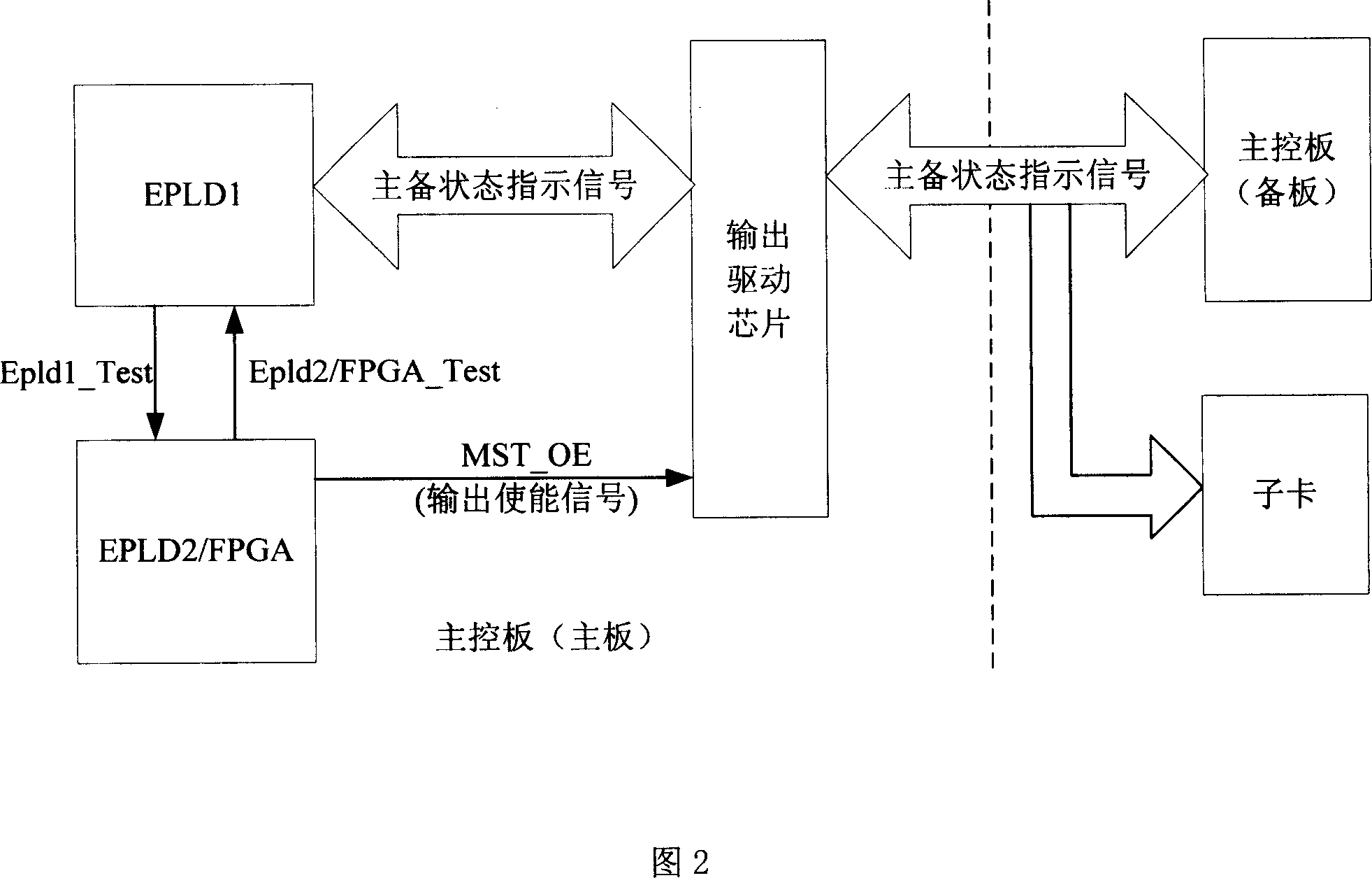
[0035] Referring to FIG. 2 , EPLD1 and EPLD2 / FPGA (Field Programmable Gate Array, Field Programmable Gate Array) perform mutual inspection. Among them, EPLD1 is the main logic control chip originally responsible for the spurious control function of the entire main control board. The active-standby switchover process is still completed by EPLD1, and EPLD2 / FPGA does not participate in the active-standby switchover, and is used as a designated logic control chip to detect EPLD1. EPLD2 / FPGA outputs the MST_OE signal to control the output enable of the main and standby status signals output from this board to the opposite board.

[0036] The specific mutual inspection process is as follows:

[0037] 1) EPLD1 writes the detection results of EPLD2 / FPGA into the original fault detection logic of EPLD1. After detecting an abnormal situation, EPLD1 reports an alarm and triggers reset switching. This can prevent the failure of the EPLD2 / FPGA device from affecting the execution of activ...

Embodiment 2

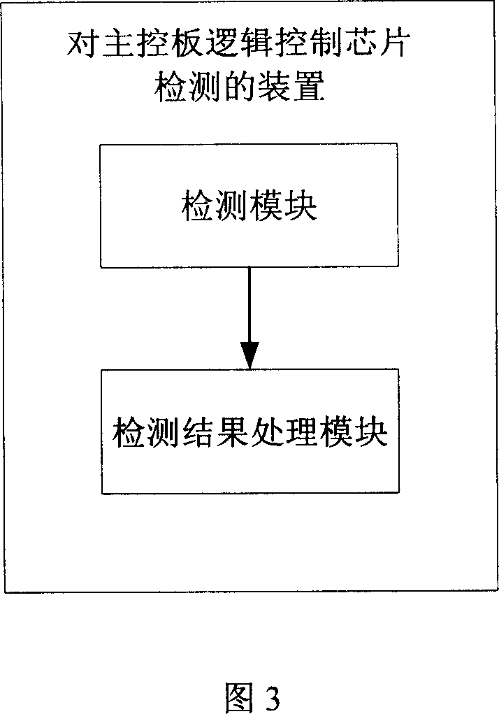
[0044] Referring to Fig. 3, the present invention also provides a device for detecting the logic control chip of the main control board, including the following modules:

[0045] The detection module is used for the designated logic control chip on the main control board to detect the main logic control chip on the main control board;

[0046] The detection result processing module is used to trigger the switchover of the active and standby boards when the designated logic control chip detects that the main logic control chip is abnormal.

[0047] In order to increase the reliability of the system, the device also includes:

[0048] The designated logic control chip detection module is used for the main logic control chip to detect the designated logic control chip and write the detection results into the original fault detection logic.

[0049] The specified logic control chip detection module is also used for reporting an alarm and triggering the switchover of the main and ...


PUM


Abstract

The invention relates to a method for checking main-control board logic control chip, and relative device, wherein said method comprises that: the pointed logic control chip of main control board checks the main logic control chip of main control board; when the check result is abnormal, it will trigger the switch between main board and backup board. The invention also provides relative device, which comprises checking module and checking result processing module.

Description

technical field [0001] The invention relates to the field of network communication, in particular to a method and a device for detecting a logic control chip of a main control board. Background technique [0002] At present, many products adopt a dual-master redundant design to improve product reliability. When a problem is detected on the main master board, the device control right can be handed over to the backup master board for management and control. Generally, an EPLD (Erasable Programmable Logic Device, Erasable Programmable Logic Device) on the main control board completes various stray control functions of the entire board, such as: fault detection, reset control, master-standby switchover, etc. After the failure of the logic chip, the control of the entire single board and even the entire system will be in a state of chaos, which will eventually lead to system failure. It can be seen from this that the logic control chip is important to the normal operation of the...

Claims


Application Information

Patent Timeline
IPC IPC(8): H04B1/74H04M3/24H04B17/00
Inventor 金敬
Owner HUAWEI TECH CO LTD
Learn More