
Clamp-proof device

An anti-clamping device and a technology of rotation angle, which is applied in the direction of transportation and packaging, elevators in buildings, etc., can solve the problems of being caught, etc., and achieve the effect of sensitive response, beautiful appearance and simple production

Inactive Publication Date: 2007-05-30
杭州西子孚信科技有限公司
View PDF1 Cites 4 Cited by
  • Summary
  • Abstract
  • Description
  • Claims
  • Application Information

AI Technical Summary

Problems solved by technology

Although the protective device plays a certain role in preventing the hand from being caught, the human hand may still be caught if there is no time to respond. In addition, if clothes and other objects are inserted into the gap, there will be no conditioned reflex, so it cannot fundamentally Solve the problem

Method used


Image

  • Clamp-proof device
  • Clamp-proof device

Examples


Embodiment Construction

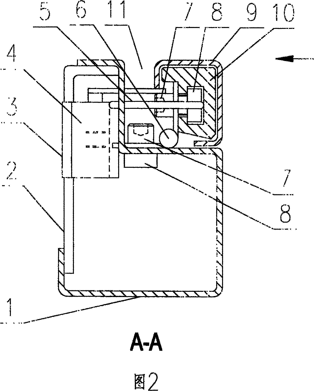
[0014] Referring to Fig. 1 and Fig. 2, this embodiment includes a main frame 1, a hinge 6, a rotating angle steel 9, a micro switch 4 and a return spring 5, wherein the main frame 1 is connected with the rotating angle steel 9 through a hinge 6 to form a Turn mechanism. There are installation holes on the main frame 1, and the screws 7 pass through the holes to connect with the double-hole nuts 8, and the main frame 1 and the hinge 6 are fixedly connected together, and the angle steel lining 10 is installed in the rotating angle steel 9, and the angle steel lining 10 There is a groove, and the double-hole nut 8 is placed in the groove, and then the rotating angle steel 9 and the hinge 6 are fixedly connected together by the screw 7 and the double-hole nut 8 . One end of the return spring 5 passes through the reserved hole on the main frame 1, and its other end is positioned in the groove on the angle steel lining 10, so that the rotating angle steel 9 is flexibly reset, and un...


PUM


Abstract

It relates to the anti clamping device for the automatic sliding door of lifters. It comprises the main frame, hinges, rotary corner steel, inching switch and reset spring, with the hinge fixed with the main frame and rotary corner steel respectively, with the rotary corner steel rotates around the main frame, inching switch and the reset spring on the main frame and the rotary corner steel driving the inching switch to motion. This simple, convenient and reliable device solves the clamping issue of lifter sliding doors, eliminating potential risks in national lifter regulations.

Description

technical field [0001] The invention relates to an anti-pinch device, which is mainly used for automatic sliding doors of elevators. Background technique [0002] Article 7.5.1 of GB7588-2003 "Safety Code for Elevator Manufacturing and Installation" stipulates: "The design of the landing door and its surroundings should minimize the risk of damage or injury caused by people, clothes or other objects being caught. In order to avoid Risk of shearing during operation, power-operated automatic sliding doors shall have no recesses or protrusions greater than 3 mm on the outer surface, and the edges of these recesses or protrusions shall be chamfered in the direction of door opening travel". Since there is still a certain movement gap between the door leaf and the column, Article 7.1 of GB7588-2003 "Safety Code for Elevator Manufacturing and Installation" also stipulates: "For passenger elevators, this movement gap shall not be greater than 6mm. For cargo elevators, this gap shal...

Claims


Application Information

Patent Timeline
Patent Type & Authority Applications(China)
IPC IPC(8): B66B13/28
Inventor 严伟东周国良钱东清王惠康韩彬
Owner 杭州西子孚信科技有限公司
Learn More