Eureka AIR delivers breakthrough ideas for toughest innovation challenges, trusted by R&D personnel around the world.

Wave jumping impeller type wave energy power generating device automatically lifting along with tide level

A technology of automatic lifting and power generation device, applied in ocean energy power generation, renewable energy power generation, hydropower generation and other directions, can solve the problems of poor applicability, limited energy absorption rate of wave energy power generation device, etc. High efficiency, simple structure, and the effect of improving efficiency

Inactive Publication Date: 2014-02-26
TIANJIN UNIV
View PDF6 Cites 0 Cited by
  • Summary
  • Abstract
  • Description
  • Claims
  • Application Information

AI Technical Summary

Problems solved by technology

[0007] The present invention aims to solve the technical problems of limited energy absorption rate and poor applicability of existing wave energy generating devices, and provides a tide-level automatic The raised and lowered sea wall jumping wave impeller type wave energy power generation device can obtain efficient energy transfer and conversion, adapt to different sea conditions in various sea areas, and make continuous and efficient development and utilization of ocean wave energy possible.

Method used


Image

  • Wave jumping impeller type wave energy power generating device automatically lifting along with tide level
  • Wave jumping impeller type wave energy power generating device automatically lifting along with tide level
  • Wave jumping impeller type wave energy power generating device automatically lifting along with tide level

Examples


Embodiment Construction

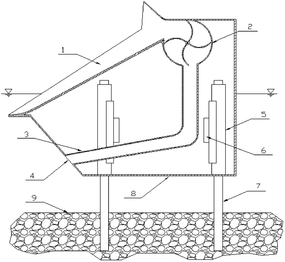
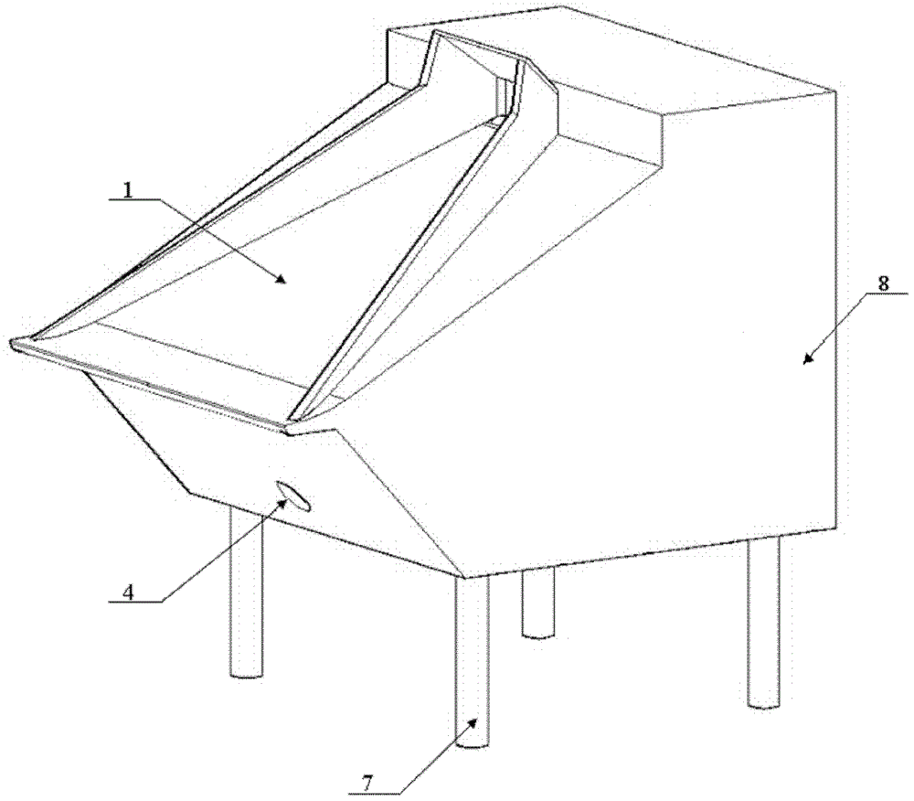
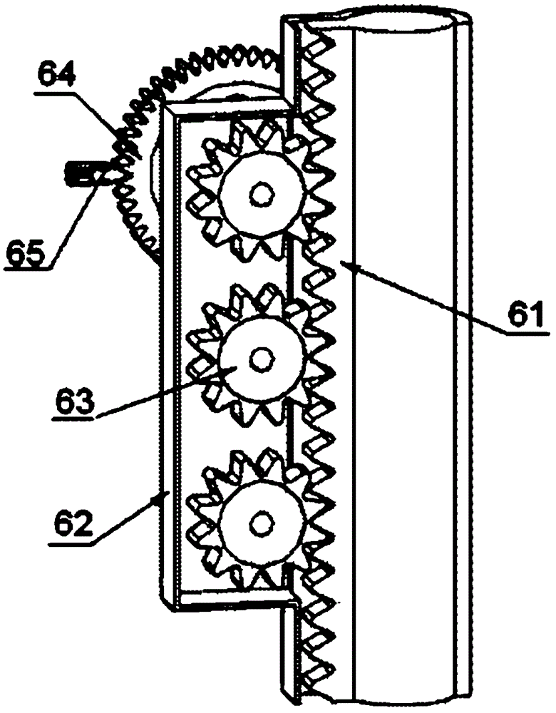
[0035] Such as figure 1 and figure 2 As shown, this embodiment discloses a wave-jumping impeller-type wave energy generating device that automatically rises and falls with the tide level, including a wedge-shaped shrinking channel 1, a wave energy collection and conversion device 2, a drainage pipe 3, a buoyancy tank 8 and related structures, Gearbox lifting and stabilizing system6. Wherein, the wave energy collection and conversion device 2 is a device for converting the collected waves into other forms of energy. The wave energy collection and conversion device 2 is installed in the buoyancy tank 8, and a water inlet is arranged on the oblique upper part of the side facing the leaping waves.

[0036] The buoyant tank 8 is a casing with a slope on its upper surface, except for the water outlet 4 of the mentioned wedge-shaped body shrinkage channel 1 and the drainage pipe 3, the remainder is designed as a sealed structure. Therefore, the buoyancy box 8 and the wave energy ...


PUM


Abstract

The invention discloses a wave jumping impeller type wave energy power generating device automatically lifting along with the tide level. The wave jumping impeller type wave energy power generating device comprises a wave energy collecting and converting device to which a wedged body shrinkage wave path and a water draining pipeline are connected, wherein the wave energy collecting and converting device is mounted inside a buoyancy tank; the wedged body shrinkage wave path is arranged on the slope of the surface of the buoyancy tank and is communicated with a water inlet of the wave energy collecting and converting device; one end of the water draining pipeline is communicated with a water outlet of the wave energy collecting and converting device; the other end of the water draining pipeline is communicated with a water draining port arranged in the buoyancy tank; pile holes through which piles penetrate are uniformly distributed on the bottom surface of the buoyancy tank; the bottoms of the piles are fixed to base rock; the upper parts of the piles extend in pile sleeves arranged inside the buoyancy tank; the bottoms of the pile sleeves are fixedly sealed with the buoyancy tank; gearboxes which are internally provided with lift gears are connected to the pile sleeves in a sealing way; and the lift gears are meshed with lift racks fixed on the piles. The wave jumping impeller type wave energy power generating device disclosed by the invention can be arranged in different sea areas, adapts to various sea conditions and can automatically and stably adjust elevation along the fluctuation of the tide level so as to ensure the function of power generating efficiency.

Description

technical field [0001] The invention relates to the development and application of ocean wave energy in the technical field of renewable energy, in particular to a power generation device utilizing wave energy generated by ocean energy. Background technique [0002] In recent years, driven by the depletion of fossil energy, energy supply security, environmental protection and ecological balance, people have paid more and more attention to the development of new energy. 71% of the earth's surface area is the ocean with huge energy resources, among which wave energy is one of the most abundant energy resources in ocean energy. Utilizing marine energy has become the direction of energy research in the world today, and how to effectively utilize abundant and renewable marine resources is even more important. In 1992, the United Nations listed wave power generation as the top priority in the development of marine renewable energy. Coastal countries attached great importance to i...

Claims


Application Information

Patent Timeline
Patent Type & Authority Patents(China)
IPC IPC(8): F03B13/22F03B15/14F03B3/12
CPCY02E10/38Y02E10/223Y02E10/20Y02E10/30
Inventor 李大鸣王志超白玲
Owner TIANJIN UNIV
Why Eureka
Eureka Blog
Learn More