Pulley yoke tangential constraining device

A technology of restraint device and pulley frame, which is applied in the field of aviation test, can solve the problems of failure to meet the test piece assessment, support fixture damage, etc., and achieve the effect of simple structure, low cost and convenient operation

Active Publication Date: 2016-08-31
XIAN AIRCRAFT DESIGN INST OF AVIATION IND OF CHINA
View PDF3 Cites 0 Cited by
  • Summary
  • Abstract
  • Description
  • Claims
  • Application Information

AI Technical Summary

Problems solved by technology

The disadvantage of this method is that it brings damage to the support fixture, which may cause the support fixture to be damaged earlier than the test piece and fail to achieve the purpose of evaluating the test piece

Method used


Image

  • Pulley yoke tangential constraining device
  • Pulley yoke tangential constraining device
  • Pulley yoke tangential constraining device

Examples


Embodiment Construction

[0020] In order to make the objectives, technical solutions and advantages of the present invention clearer, the technical solutions in the embodiments of the present invention will be described in more detail below in conjunction with the drawings in the embodiments of the present invention. In the drawings, the same or similar reference numerals denote the same or similar elements or elements having the same or similar functions throughout. The described embodiments are some, but not all, embodiments of the invention. The embodiments described below by referring to the figures are exemplary and are intended to explain the present invention and should not be construed as limiting the present invention. Based on the embodiments of the present invention, all other embodiments obtained by persons of ordinary skill in the art without making creative efforts belong to the protection scope of the present invention. Embodiments of the present invention will be described in detail b...


PUM


Abstract

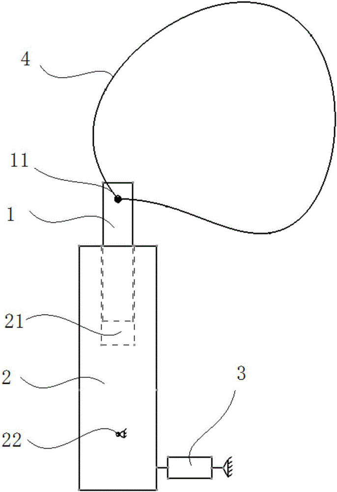
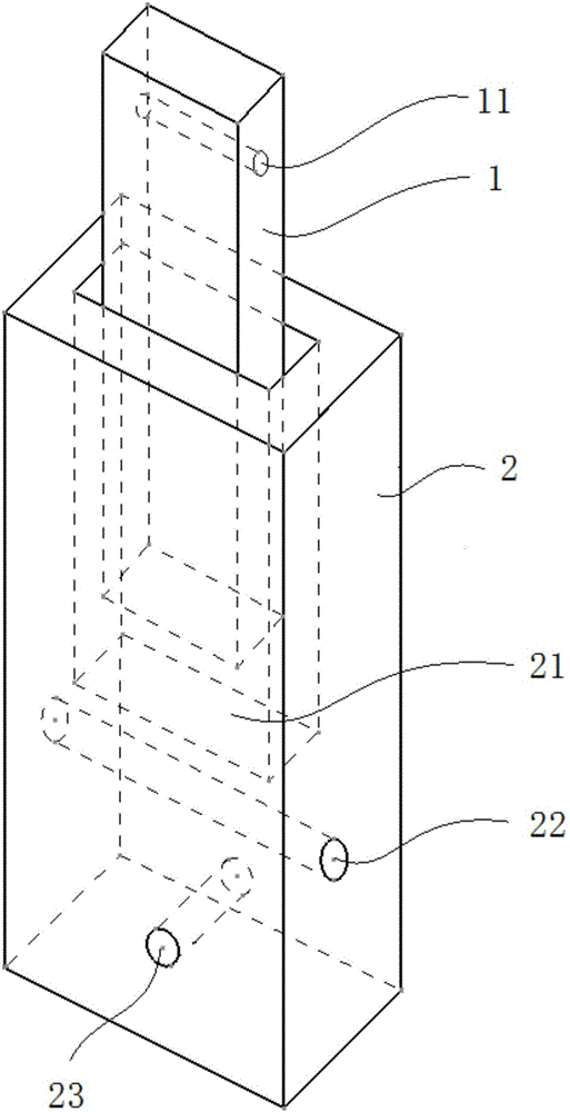
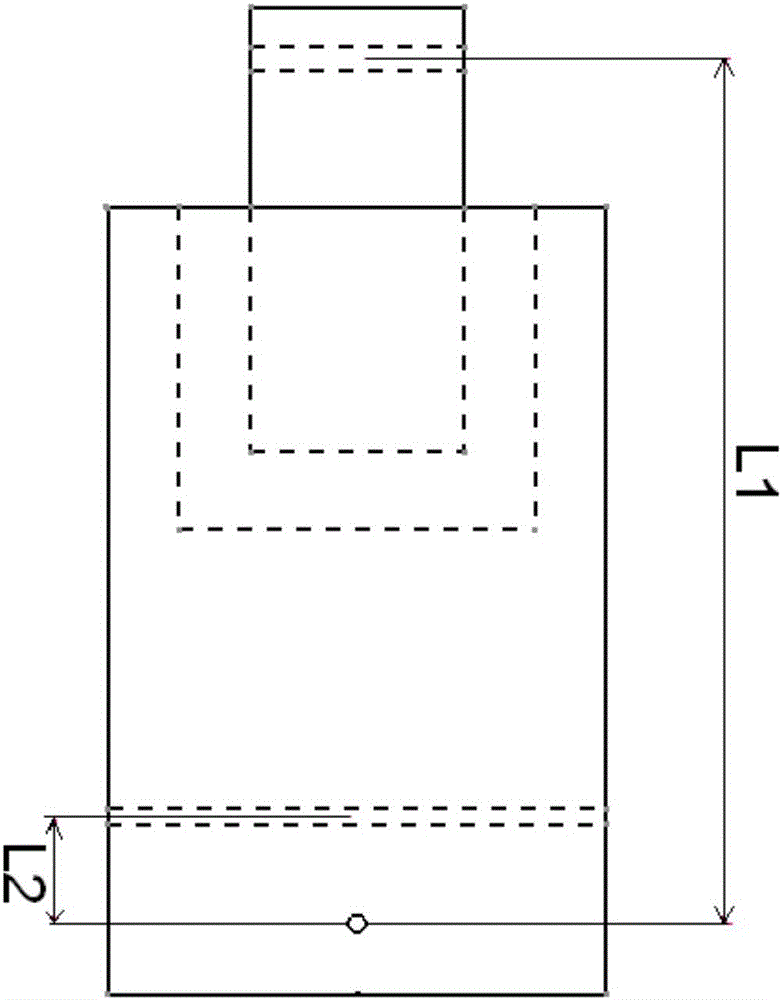
The invention relates to a pulley yoke tangential constraining device which is used for tangentially constraining a pulley yoke during pulley yoke strength test. The device comprises a slide block, a constraining block, and a constraining device. One end of the slide block is provided with a pin hole, the axis of the pin hole is perpendicular to the plane wherein a pulley yoke is located, the slide block and the pulley yoke are relatively fixed by a connector, and the slide block and the pulley yoke rotate about the axis of the pin hole. The upper end of the constraining block is provided with a chute, the other end of the slide block is placed in the chute and slides relative to the constraining block, the lower end of the constraining block is provided with a fixed hole, the axis of the fixed hole is parallel to the axis of the pin hole, and the constraining block and a test bench are fixed by a connector. One end of the constraining device is fixed to a datum plane, the other end acts on the constraining block, and the acting force shifts on the plane wherein the pulley yoke is located. The pulley yoke tangential constraining device of the invention is applied to slide rail pulley yoke test. In addition to tangentially constraining a pulley yoke without damaging a support fixture, the device can measure the tangential constraining force. The device has the advantages of simple structure, smart design, convenient operation, low cost, and the like.

Description

technical field [0001] The invention belongs to the technical field of aviation test, in particular to a tangential restraint device of a pulley frame. Background technique [0002] At present, the slide rail and pulley frame system is used in mechanisms that need to be frequently deployed or retracted. Without external constraints, the pulley frame usually can only slide freely along the tangential direction of the slide rail. In the strength test of the pulley frame, it is necessary to load the pulley frame on the basis of keeping the position of the pulley frame and the slide rail relatively fixed. The current way is to insert pins after drilling holes on the slide rail, and block the pulley frame with the pins so that the pulley frame cannot move along the slide rail. The disadvantage of this method is that it brings damage to the support fixture, which may cause the support fixture to be damaged earlier than the test piece, so that the purpose of evaluating the test pi...

Claims


Application Information

Patent Timeline
Patent Type & Authority Applications(China)
IPC IPC(8): G01M13/00
CPCG01M13/00
Inventor 鬲钰焯范瑞娟李健
Owner XIAN AIRCRAFT DESIGN INST OF AVIATION IND OF CHINA
Why Eureka
Try Eureka