Jet fan for airflow movement

A technology for conveying airflow and jet flow, which is applied to the components of pumping devices for elastic fluids, engine working fluid, thin plate connections, etc., and can solve problems such as power consumption, running noise, deterioration, and harmful health

Inactive Publication Date: 2007-05-30
DAEWOO SHIPBUILDING & MARINE ENG CO LTD +1
View PDF0 Cites 4 Cited by
  • Summary
  • Abstract
  • Description
  • Claims
  • Application Information

AI Technical Summary

Problems solved by technology

[0003] In the above-mentioned factories, the processing materials produce a large amount of welding fume, dust, gas, etc., which can change the working environment and harm the health of workers. Therefore, more attention should be paid to the ventilation inside the factory. However, because most factories simply Relying on rotary electric fans to perfo...

Method used


Image

  • Jet fan for airflow movement
  • Jet fan for airflow movement
  • Jet fan for airflow movement

Examples


Embodiment Construction

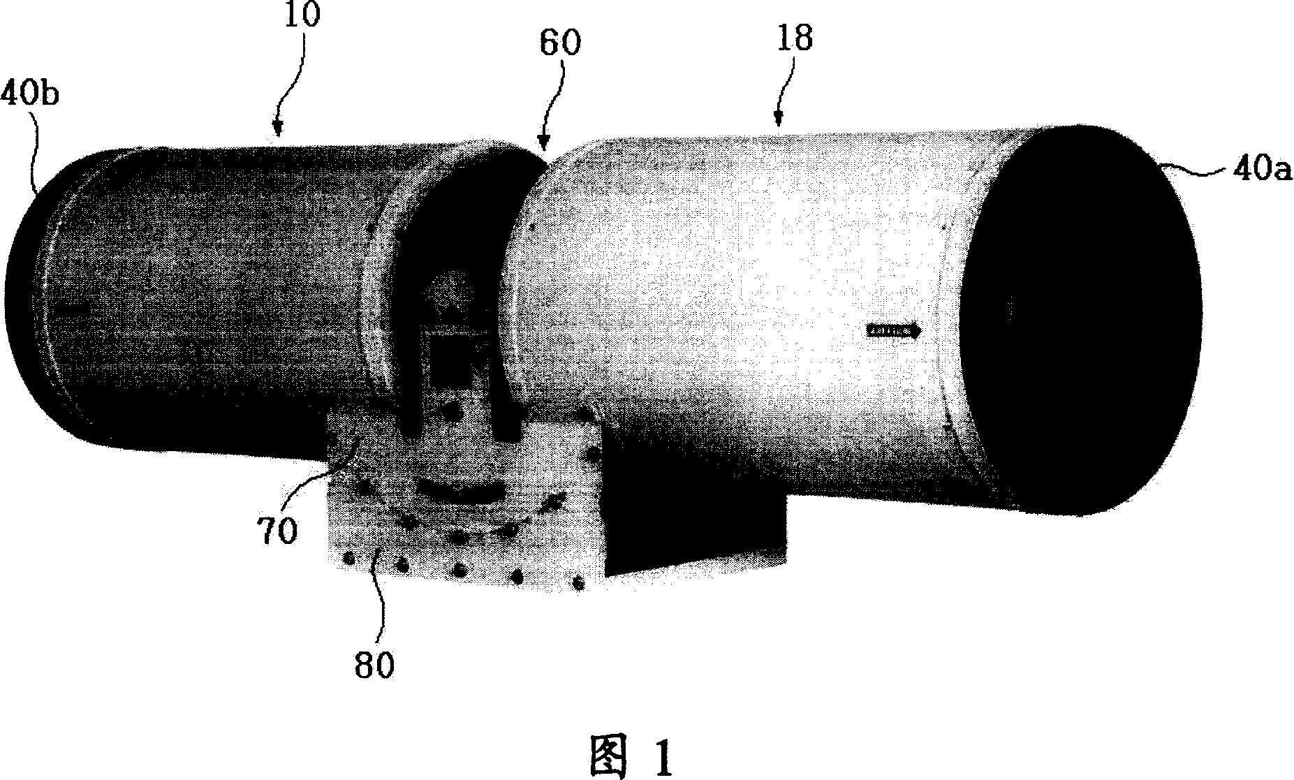
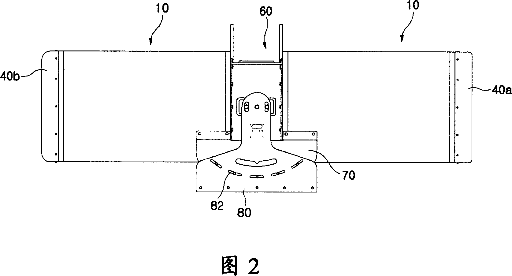
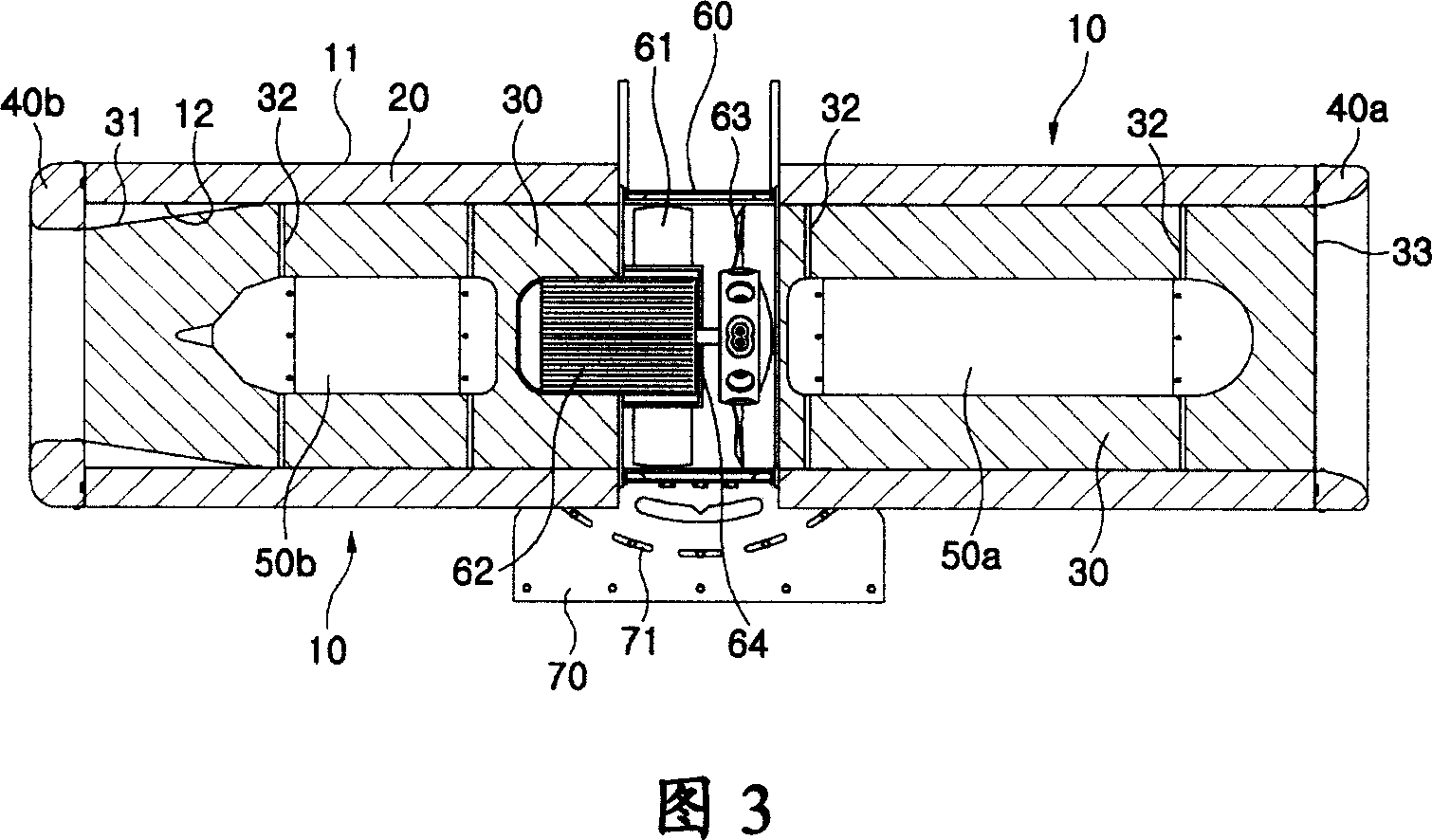
[0022] The present invention includes: two separate housings 10, arranged oppositely in the shape of cylinders, composed of an outer cylinder 11 and an inner cylinder 12 with a smaller diameter than the outer cylinder 11. The outer cylinder 11 and the inner cylinder 12 are A sound-absorbing element 20 for absorbing noise is provided in between; the containing pipe 30 is formed in the form of a perforated plate and is closely contained within the entire inside of the cylindrical body 12 of the housing 10, and is integrated on the inside of the front end of the discharge-side housing 10 A nozzle portion 31 with a gradually smaller diameter is formed; the introduction-side silencer 50a and the discharge-side silencer 50b are respectively located in the central part of the inner side of the housing pipe 30 of the above-mentioned separated housing 10, and both sides are passed through silencer bolts 32 is supported and fixed on the inner wall of the receiving pipe 30; the introduction ...


PUM


Abstract

The invention relates to a jet fan for airflow movement including: two separated casings (10) composed of an exterior column (11) and an interior column (12), between which a sound deadening member (20) is provided; a accommodated tube (30) formed of polyporous plate shape and having a nozzle (31) with little livly diameter; an internal wall supported and fixed in the accommodated tube (30) for introducing the side silencer (50a) and discharging the side silencer (50b); introducing the side lid (40a) and discharging the side lid (40b); a fan box (60), in which, the motor is provided and the impeller (63) is rotated by the motor; a supported bracket (70) fixed on the two side bottom of the casing, and a plurality of feed holes are formed of arc shape with the center of the fan box (60) as reference; a fixing member whose elongation part (81) has a plurality of angle adjustment hole (82). The invention is used for introducing to deliver and exhaust air, introducing ventilation and controlling airflow pattern, and the factory is ventilated swimmingly.

Description

Technical field [0001] The invention relates to a jet fan for conveying air flow. The present invention is installed in single-type and conjoined semi-open factories in shipyards and other heavy industry fields that inevitably generate welding fumes, dust, exhaust gas, etc., to guide air supply and exhaust, guide ventilation, and control air flow spectrum , Which can smoothly ventilate the above-mentioned factories. Background technique [0002] Usually, shipyards and other heavy industry factories have large-scale single-unit and conjoined factories for indoor operations. [0003] In the above-mentioned factories, the processed materials produce a large amount of welding fumes, dust, gas, etc., which can change the working environment and are harmful to the health of workers. Therefore, it is necessary to pay more attention to the ventilation inside the factory. However, because most factories are simple Rotary electric fans are used to ventilate the inside of the factory. There...

Claims


Application Information

Patent Timeline
IPC IPC(8): F04D25/12F04D29/66F04D29/52F04D29/70F04D29/64
CPCF04D25/08F04D29/002F04D29/38F04D29/403F04D29/664F05D2210/12F16B5/02Y10S415/00Y10S417/00
Inventor 慎承叙林润彻
Owner DAEWOO SHIPBUILDING & MARINE ENG CO LTD
Why Eureka
Try Eureka