Ratio-variable feedback type digital fluid cylinder

A fluid cylinder, feedback technology, applied in the direction of fluid pressure actuation devices, etc., can solve the problems of complex control system, reduced working speed of digital cylinder, and reduced positioning accuracy.

Inactive Publication Date: 2007-05-30
成都电子机械高等专科学校 +2
View PDF0 Cites 18 Cited by
  • Summary
  • Abstract
  • Description
  • Claims
  • Application Information

AI Technical Summary

Problems solved by technology

In the existing digital hydraulic cylinder technology, a single feedback lever is used for control, and there is always a contradiction between motion speed and positioning accuracy. Since the feedback uses a directly connected feedback lever, the feedback speed at the feedback signal collection point and the output point of the feedback signal The speed ratio is only 1:1
That is to say, in the case of constant NC signal frequency, to obtain high speed, it is necessary to increase the pulse equivalent. The most direct way is to increase the helical lead of the piston nut and the feedback screw, and the piston advance speed can be increased. However, this method The positioning accuracy is reduced; similarly, in order to obtain high positioning accuracy, it is necessary to reduce the pulse equivalent. If the screw lead of the piston nut and the feedback screw is reduced, the positioning accuracy requirements are met, but at the same time the digital cylinder Reduced work speed
This contradiction between speed and precision cannot be overcome from the structure itself in the existing scheme, which greatly limits the promotion and use of digital hydraulic cylinders
The existing solution is to use a complex control system, increase the pulse frequency, and increase the movement speed, thereby indirectly compensating for structural defects
Due to the limitation of the direct starting frequency of the stepping motor and the structure of the hydraulic cylinder, the entire control system becomes complicated and the cost increases significantly. It is difficult to achieve the unity of high precision and high speed at the same time. The bottleneck of the industrial application of hydraulic cylinders makes it difficult to obtain widespread promotion

Method used


Image

  • Ratio-variable feedback type digital fluid cylinder
  • Ratio-variable feedback type digital fluid cylinder
  • Ratio-variable feedback type digital fluid cylinder

Examples


Embodiment 1

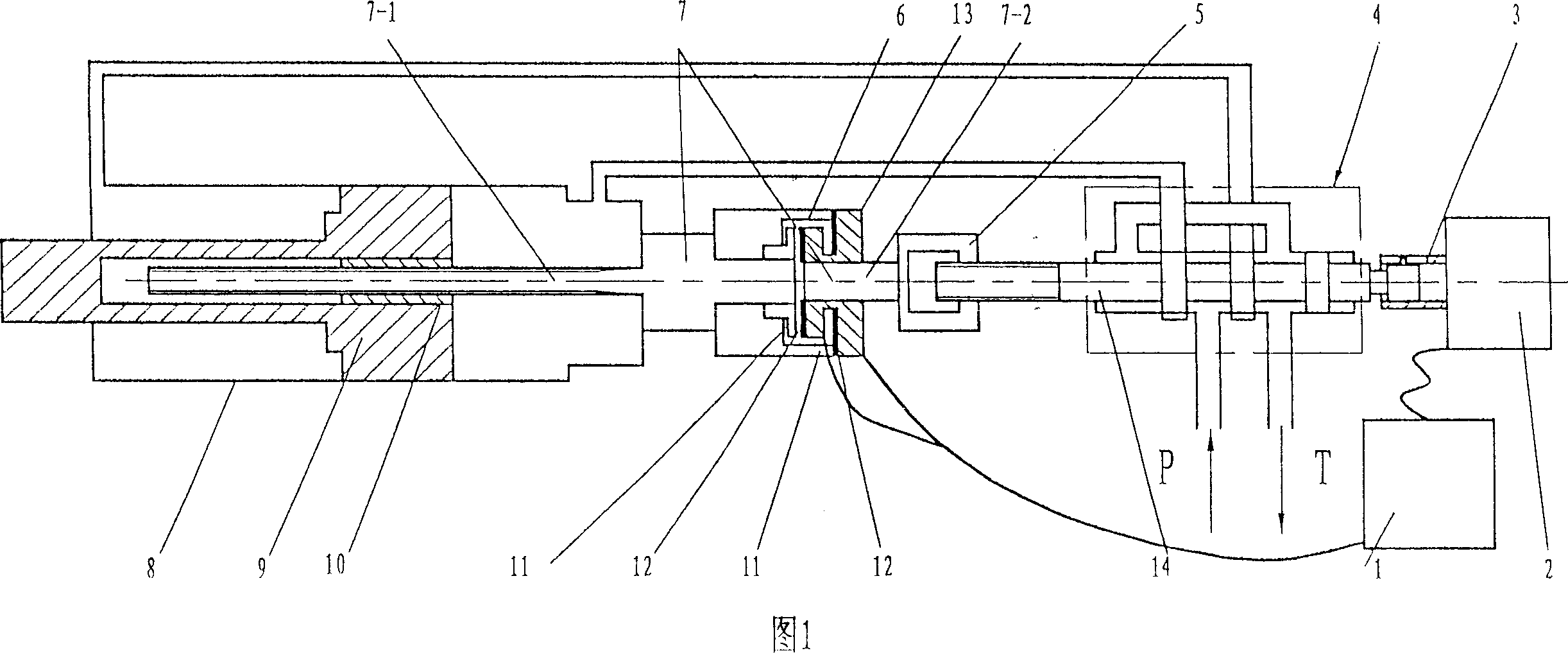
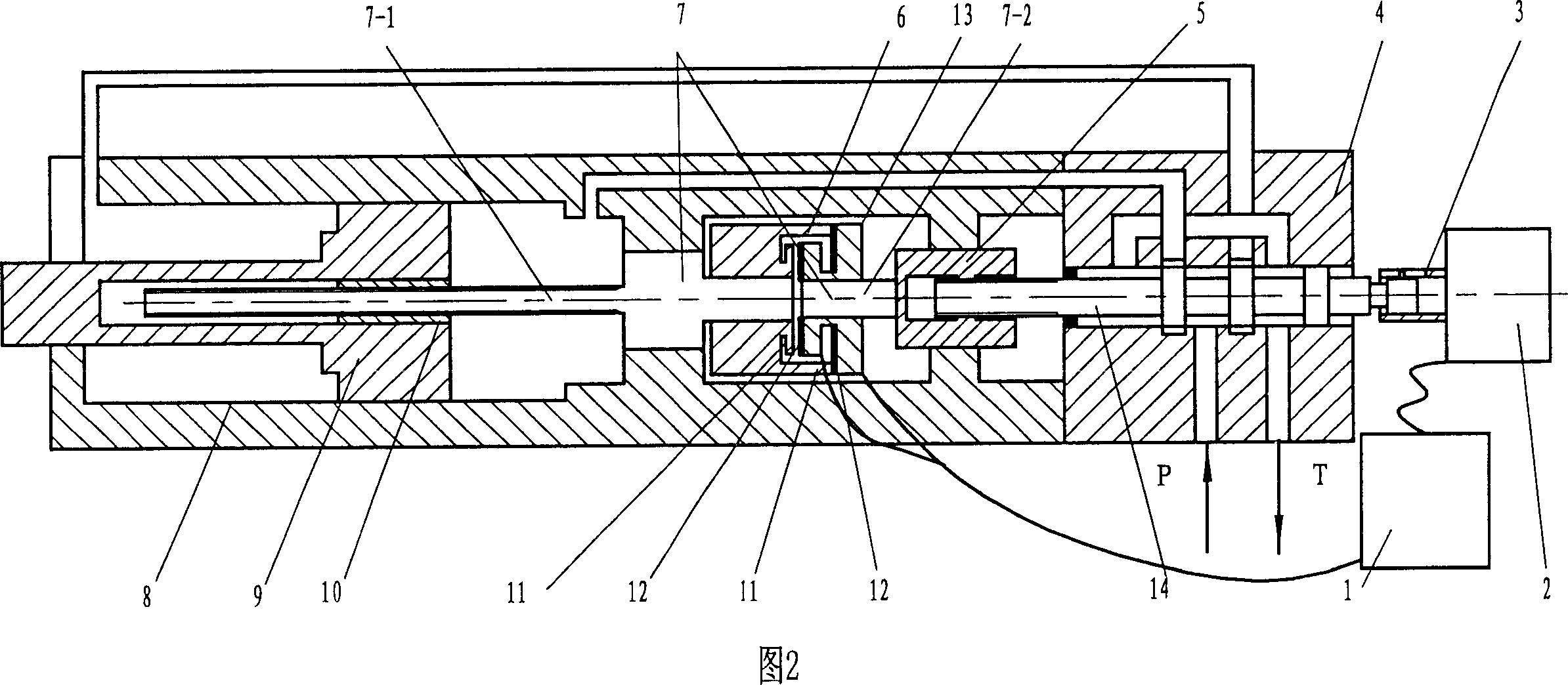
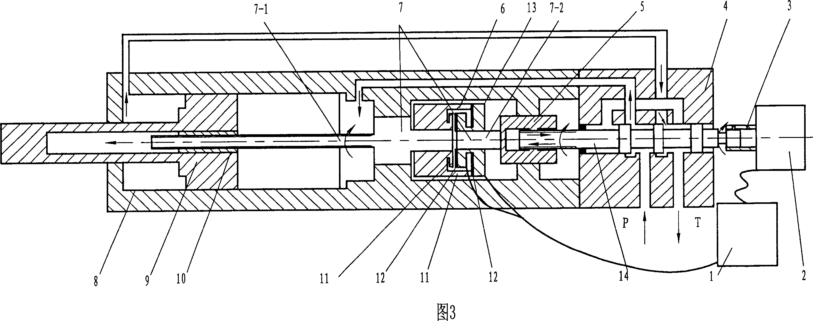
[0038] The variable ratio feedback type digital fluid cylinder of the present invention includes the parts and structures that the existing numerical control fluid cylinder also has: a numerical control device 1, a control drive motor 2, a cylinder body 8, and a piston 9 in the cylinder body 8, and a control valve 4 And the feedback lever 7, the control valve spool 14 is connected with the control drive motor 2 in the way of rotating the sliding sleeve 3, and the control valve 4 is a spool valve. The function of the control valve 4 is to realize the control of the start and stop of the piston movement and the change of the movement direction. The present embodiment controls the stepper motor for driving the motor 2 . The feedback mechanism in the present embodiment digital fluid cylinder is:

[0039] The feedback rod of the present invention is made up of two sections, wherein on a section adjacent to the piston 9 is a piston-end feedback rod 7-1, and one end of the piston-en...

Embodiment 2

[0045] Like Embodiment 1, the only difference is that the speed output end 11 of the transmission device and the clutch terminals 12 of the clutch 13 are different in number and relative proportion. The three speed output terminals 11 ball bearing transmissions are replaced by five speed output terminals 11 gear transmissions, that is, the five speed output terminals 11 of A, B, C, D, E, wherein, the A terminal and the piston end feedback rod 7-1 is directly connected, and the speed ratio of the rotational speed of the A terminal to the rotational speed of the feedback rod at the piston end is 1:1. Electromagnetic clutch 13 also has U, W, X, Y, Z five clutch terminals 12 that can be engaged with these five speed output terminals 11 respectively.

[0046] The feedback rod 7-2 at the control valve end is connected with the control valve 4 through the connection sleeve 5 in a spiral pair.

[0047] The output speeds of the five speed output terminals 11 of gear transmission devic...

Embodiment 3

[0056] As in embodiment 1, but the ball bearing speed changer with three speed output ends 11 is replaced by a friction wheel speed changer with two speed output ends 11 A and B, wherein the A terminal is directly connected to the feedback rod 7-1 at the piston end , the speed ratio is 1:1. Any one of the reciprocating speeds of the piston 9 can have two different rotational speed outputs at the speed output end 11 of the friction wheel speed changer. Sure. For example, when the reciprocating positioning accuracy of the piston 9 is 0.01 mm, the speed ratio of the two rotational speeds of the friction wheel speed changer can be 1:4. If the output speed of terminal A is 100 rpm, the speed of terminal B is 400 rpm.

[0057] The electromagnetic clutch 13 also has two clutch terminals 12, X and Y, engaged with the speed output end 11, and the clutch terminals 12 are respectively controlled by corresponding electromagnets to engage or disengage. Each electromagnet is connected to...


PUM


Abstract

The invention relates to a digital fluid cylinder with transformer ratio feedback, belonging to fluid cylinder technology area, especially feedback control technology of self-feedback digital driving hydraulic cylinder. As the piston of fluid cylinder moves in high speed and locates precisely. Feedback bar 7 in fluid cylinder is divided into feedback bar of piston 7-1 and feedback bar of control valve 7-2 and at one end of the feedback bar of piston 7-1 transmission 6 is set. Clutch 13 is set at one end of the feedback bar of controller 7-2 and set at the position where the clutch 13 is joined with the transmission 6. NC device 1 controls the running of driving motor 2 and different clutch terminals 12 of clutch 13 to join and release with the transmission 6. The piston journey is divided into high speed moving segment of long distance and low speed accurate moving segment of micro distance by NC device. In different moving segment different clutch terminal 12 is started so that the core of control valve 14 obtains different feedback energy and different moving speed and located accuracy of piston are controlled.

Description

technical field [0001] The invention belongs to the technical field of fluid cylinders, in particular to the technical field of feedback control of self-feedback digital drive hydraulic cylinders. Background technique [0002] Digital hydraulic cylinder technology fully embodies the characteristics and advantages of digital hydraulic technology. It originated in the 1960s and 1970s. Due to the continuous research and improvement in this field in Germany, Japan and China, digital fluid cylinder technology has gradually reached practical stage. [0003] The existing practical digital cylinder consists of a numerical control device, a stepping motor and a cylinder with a control valve. The function of the control valve is to control the start, stop and direction of motion of the cylinder piston. The basic working principle of the digital hydraulic cylinder is that the microcomputer sends out a control pulse sequence signal, which is amplified to drive the stepping motor to mov...

Claims


Application Information

Patent Timeline
Patent Type & Authority Applications(China)
IPC IPC(8): F15B15/14F15B15/20
Inventor 洪明宋鸣
Owner 成都电子机械高等专科学校
Why Eureka
Try Eureka