Testing method of thermal resistance of heat-conducting material and testing clamp

A technology of heat-conducting materials and testing methods, which is applied in the field of testing, can solve problems such as poor test result accuracy, elevated temperature of the workbench, and the inability to put heat-conducting materials into the environmental test chamber, so as to achieve the effect of improving test accuracy

Inactive Publication Date: 2007-05-30
HUAWEI TECH CO LTD
View PDF0 Cites 47 Cited by
  • Summary
  • Abstract
  • Description
  • Claims
  • Application Information

AI Technical Summary

Problems solved by technology

[0008] 1. Since the thermal resistance test device of the heat-conducting material is a whole that cannot be disassembled, the heating block and the workbench cannot be separated, and the heat-conducting material cannot be put into the environmental test chamber after being fixed on the workbench of the test instrument, resulting in the failure of the test device. It can only be used at room temperature, and the thermal conductive material cannot be tested under various environmental conditions such as temperature and time, so the long-term reliability of the thermal conductive material cannot be evaluated
[0009] 2. Since the test process is carried out under no wind conditions, if the heat of the lower workbench cannot be dissipated in time, the temperature of the workbench will accumulate and rise, resulting in poor test result accuracy

Method used


Image

  • Testing method of thermal resistance of heat-conducting material and testing clamp
  • Testing method of thermal resistance of heat-conducting material and testing clamp
  • Testing method of thermal resistance of heat-conducting material and testing clamp

Examples


Embodiment Construction

[0031] Below according to accompanying drawing and embodiment the present invention will be described in further detail:

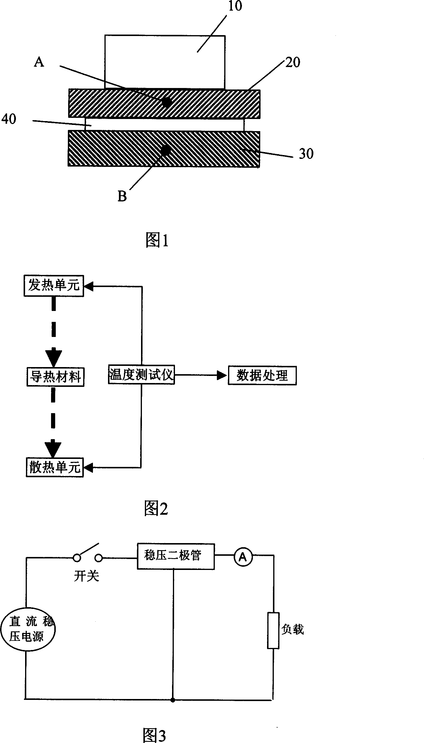
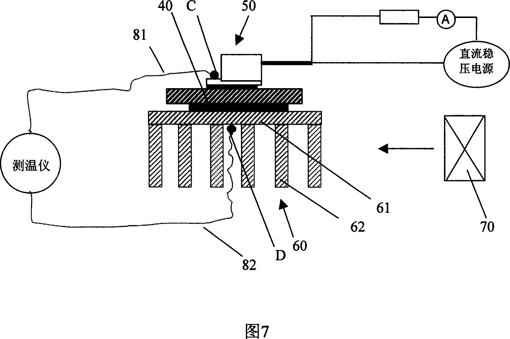
[0032] As shown in Figure 2 and Figure 7, the present invention provides a method for testing the reliability of thermal resistance of thermally conductive materials, comprising the following steps:

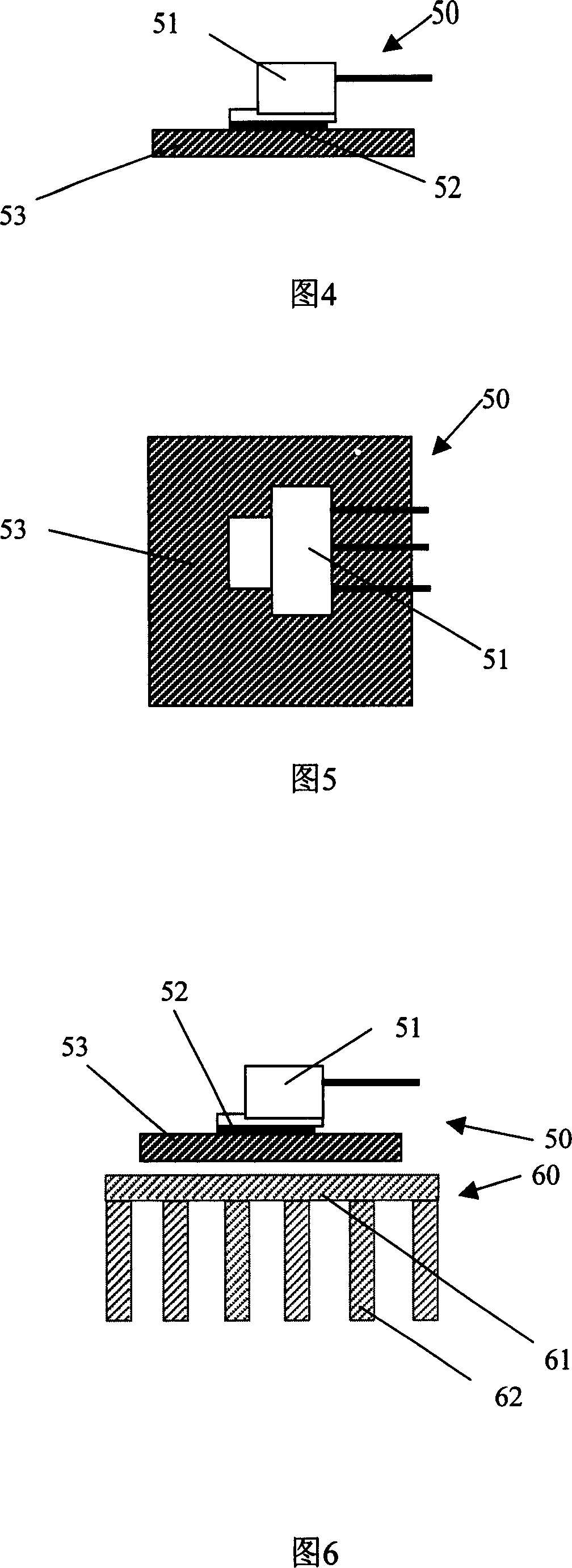
[0033] A test fixture that can be placed in an environmental test chamber consisting of a heating unit 50 and a heat dissipation unit 60 is provided, and the heat conducting material 40 is clamped between the heating unit 50 and the heat dissipation unit 60;

[0034] Put the test fixture holding the heat-conducting material 40 into the environmental test chamber, and set the parameters of the environmental test chamber to carry out the environmental test;

[0035] Take out the test fixture from the environmental test chamber, start the test after cooling to normal temperature, heat the heating unit 50 and conduct the heat to the heat dissipation unit 60 throu...


PUM


Abstract

A testing method for thermal resistance of heat conducting material is disclosed. The testing jig which consist of heating unit and dissipating heat unit is set, the heat conducting material is clipped between the heating unit and dissipating heat unit; the testing jig clipping the heat conducting material is located in the environmental test box, and the parameters of the environmental test box is set to do environmental test; the testing jig tested by the environmental test is heated by the heating unit, the heat is transferred to the dissipating heat unit through the heat conducting material, the temperature of the heating unit and dissipating heat unit is measured; when the temperature is stable, the thermal resistance is calculated by calculating the power consumption of the heating unit and the temperature difference of the heating unit and dissipating heat unit. In the invention the testing jig which consists of the heating unit and dissipating heat unit is provided. The invention can test the reliability of the thermal resistance in different condition and improve the measuring accuracy.

Description

technical field [0001] The invention relates to the technical field of testing, in particular to a method for testing the thermal resistance of a heat-conducting material and a testing fixture. Background technique [0002] With the increasing power and miniaturization of electronic devices, the heat dissipation and insulation of electronic devices have brought severe challenges. The treatment design of the thermal interface is extremely important to prolong the life of the heat-generating device and enhance its reliability. [0003] Thermal design When simulating and designing heat dissipation schemes, the performance of thermally conductive materials is often regarded as an invariant, but in fact, thermally conductive materials are basically used in high-temperature states or high-low temperature cycles, and thermally conductive materials are used in high-temperature states for a long time Excessive seepage of silicone oil will cause problems such as drying out and separa...

Claims


Application Information

Patent Timeline
Patent Type & Authority Applications(China)
IPC IPC(8): G01N25/20
Inventor 习炳涛朱爱兰
Owner HUAWEI TECH CO LTD
Why Eureka
Try Eureka