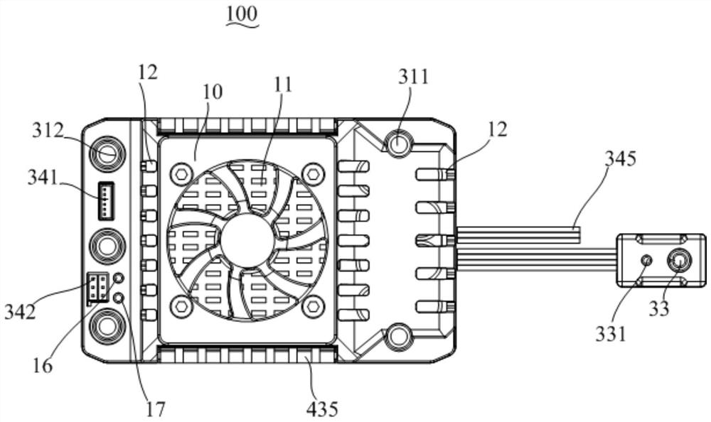
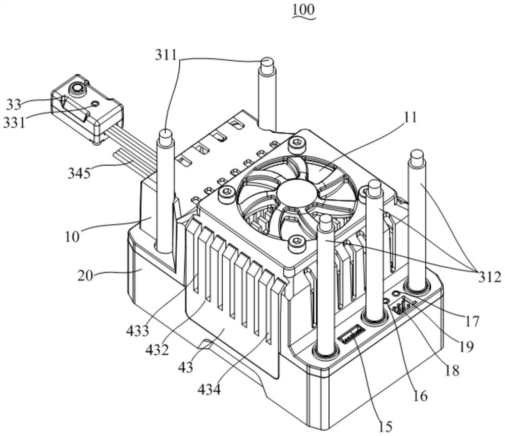
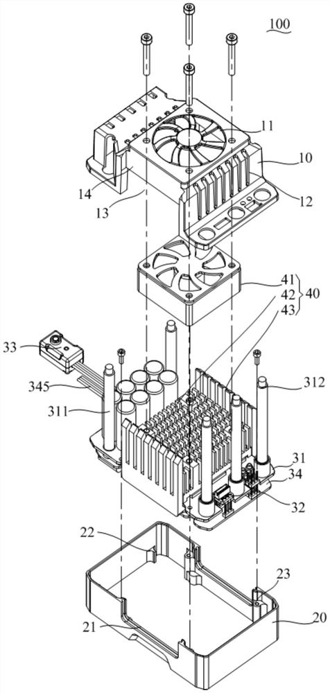
Electronic speed regulator and electronic driving device

A technology of electronic governor and housing, which is applied to the structural components of electrical equipment, electrical equipment shells/cabinets/drawers, electrical components, etc., can solve problems such as insufficient heat dissipation, burnout, and overheating protection of electronic governors, and achieve The effect of increasing the heat dissipation area, facilitating disassembly, convenient cause investigation and maintenance and quick replacement

Inactive Publication Date: 2021-08-17
SHENZHEN FLYCOLOR ELECTRONICS
View PDF0 Cites 1 Cited by
  • Summary
  • Abstract
  • Description
  • Claims
  • Application Information

AI Technical Summary

Problems solved by technology

[0003] At present, most of the high-power electronic speed controllers on the market (200-300A current and voltage above 50V) are equipped with an aluminum alloy radiator on one side of the power tube, and a fan is installed on the radiator to dissipate heat from the electronic speed controller. If it is small There is no problem with the power electronic speed controller, but when the power is very large (200-300A, current 50V or more), and the size of the electronic speed controller remains the same, such heat dissipation is not enough, and continuous high-power output The speed of heat dissipation is much lower than the speed of temperature rise, which eventually leads to overheating protection or overheating of the electronic governor, which greatly reduces the use time of the product, so better heat dissipation is particularly important

Method used


Image

  • Electronic speed regulator and electronic driving device
  • Electronic speed regulator and electronic driving device
  • Electronic speed regulator and electronic driving device

Examples


Embodiment Construction

[0033] The following will clearly and completely describe the technical solutions in the embodiments of the present invention with reference to the accompanying drawings in the embodiments of the present invention. Obviously, the described embodiments are only part of the embodiments of the present invention, not all of them. Based on the embodiments of the present invention, all other embodiments obtained by persons of ordinary skill in the art without creative efforts fall within the protection scope of the present invention.

[0034] In the present invention, unless otherwise specified and limited, the terms "connection" and "fixation" should be understood in a broad sense, for example, "fixation" can be a fixed connection, a detachable connection, or an integral body; It can be a mechanical connection or an electrical connection; it can be a direct connection or an indirect connection through an intermediary, and it can be an internal communication between two elements or a...


PUM


Abstract

The invention discloses an electronic speed regulator and an electronic driving device. The electronic speed regulator comprises a housing which comprises a first housing and a second housing, wherein the second housing is covered by the first housing to form an accommodation cavity; a control assembly which is arranged in the accommodation cavity and comprises a power board and a control board which are electrically connected, wherein the power board is connected with a switch to control the power board and the control board; a heat dissipation assembly which is arranged in the accommodation cavity to conduct heat dissipation on the control assembly and comprises a fan, a first heat dissipation piece and a second heat dissipation piece, wherein the first heat dissipation piece and the second heat dissipation piece are detachably connected, the first heat dissipation piece and the second heat dissipation piece clamp and fix the power board, the first shell and the fan are detachably fixed to the first heat dissipation piece, and the power board is detachably fixed to the second shell. The first housing is provided with an air inlet and an air outlet, so that the fan can suck in and blow out air. According to the technical scheme, the structure of an existing electronic speed regulator is optimized, the overall structure is convenient to disassemble, and the heat dissipation efficiency is higher.

Description

technical field [0001] The invention relates to the technical field of control equipment, in particular to an electronic governor and electronic driving equipment. Background technique [0002] The power of some motor-driven equipment (car models, aircraft models, drones, etc.) is provided by various motors, and the power output is determined by the speed of the motor, and the speed of the motor is controlled by the electronic governor. of. The general control steps are as follows: After the wireless control signal transmitted by the remote controller is received and decoded by the receiver on the device, it is transmitted to the signal input terminal of the electronic governor connected to the channel socket of the receiver. How much power is allocated to the motor by the power source connected to the other end of the controller, so as to adjust the speed of the motor. Electronic speed controllers are more and more widely used in remote control aircraft models and car mod...

Claims


Application Information

Patent Timeline
Patent Type & Authority Applications(China)
IPC IPC(8): H05K7/20H05K5/02
CPCH05K5/0217H05K7/20136H05K7/2039
Inventor 曹胜
Owner SHENZHEN FLYCOLOR ELECTRONICS
Why Eureka
Try Eureka