Magnetron sputter electrode and sputtering apparutus using the magnetron sputter electrode

A magnetron sputtering and electrode technology, which is applied in the field of sputtering devices, can solve the problems of complex and tedious adjustment operations, readjustment of magnetic components, and inability to operate, and achieves the effect of simple and easy adjustment operations.

Active Publication Date: 2011-11-02
ULVAC INC
View PDF1 Cites 0 Cited by
  • Summary
  • Abstract
  • Description
  • Claims
  • Application Information

AI Technical Summary

Problems solved by technology

[0006] However, there is a problem in the above-mentioned method, that is, because the magnetic element is placed at a fixed position between the target and the magnet assembly, once the profile of the magnetic flux must be adjusted again according to the needs such as film thickness when forming a film on the processing substrate, it cannot Do not adjust the placement of magnetic components again
In the above cases, the sputtering chamber must be returned to the atmosphere to take out the target, or the magnet assembly must be removed from the sputtering electrode, otherwise the operation will not work
Therefore, the adjustment work is complicated and cumbersome.

Method used


Image

  • Magnetron sputter electrode and sputtering apparutus using the magnetron sputter electrode
  • Magnetron sputter electrode and sputtering apparutus using the magnetron sputter electrode
  • Magnetron sputter electrode and sputtering apparutus using the magnetron sputter electrode

Examples


Embodiment 1

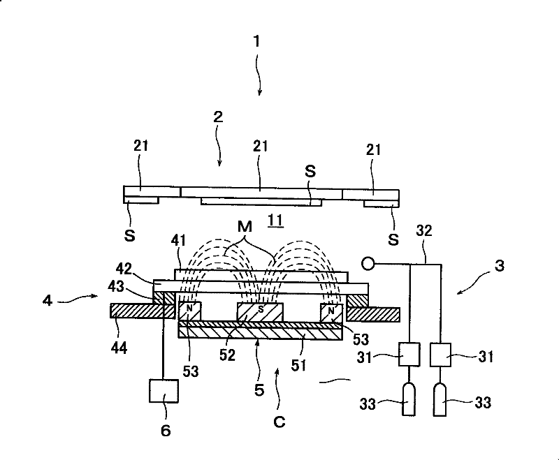
[0064] This embodiment is as Figure 6 The illustrated ITO film is formed on a processing substrate S by using a sputtering apparatus 10 . The processing substrate S is a glass substrate (1200mm×1000mm), and the targets 41α-41f are used in In 2 o 3 Add 10 wt% SnO on 2 , be made into 230mm * 1460mm external dimension and be installed on the backing plate 42 with known method. Then, an ITO film was formed on the glass substrate S by reactive sputtering.

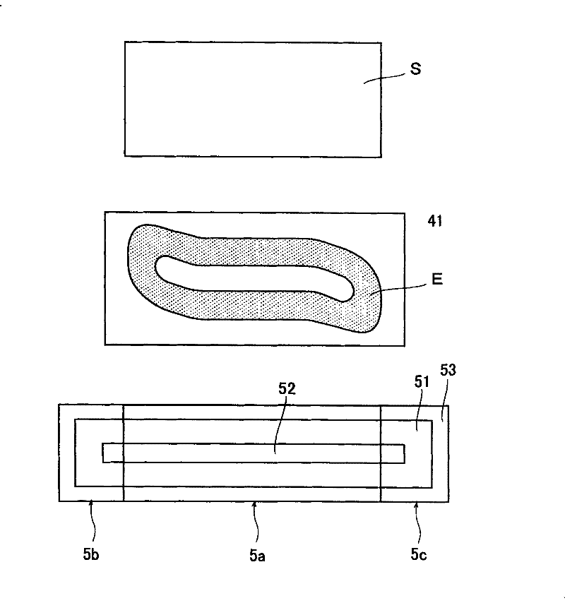
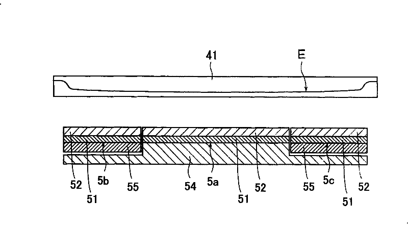
[0065] In addition, as the supporting plate 51 supported by each magnet assembly 50a-50f, the outer dimension is 130mm×1460mm, and the rod-shaped central magnet 52 along the length direction of the targets 41a-41f and the outer peripheral direction of the supporting plate 51 are arranged on each supporting plate 51. After the surrounding magnets 53 of the target 41a to 41f are separated, they are divided at positions about 40 mm from the edges in the longitudinal direction of the targets 41a to 41f. Then, by using the posi...


PUM


Abstract

The content of this invention: magnetron sputter electrode enable simply contour regulation of tubular magnet beam generate between magnet assembly parts and easy to operate. A center magnet and peripheral magnets are arranged on the support plate, tubular magnet beam magnet assembly parts in front of target are consisted. The support plate including a center magnet and peripheral magnets is divided relative to two sides, center part fixed with a base plate, other divided parts are moved relative to centre part in direction of front and back, left and right, up and down by position change apparatus which arranged on the base plate.

Description

technical field [0001] The invention provides a magnetron sputtering electrode for forming a specific thin film on a processing substrate by using a sputtering method and a sputtering device using the magnetron sputtering electrode. Background technique [0002] The sputtering device using the magnetron sputtering method refers to the rear of the target (the back side of the sputtering surface), and the magnet assembly with a plurality of magnets with alternating polarities is set on a support plate of a specific shape. The function of the magnet assembly is to form a tubular magnetic beam in front of the target (sputtering surface). By capturing electrons ionized in front of the target and secondary electrons generated by sputtering, the electron density in front of the target is increased, and the The collision ratio between electrons and noble gas molecules introduced in the vacuum chamber increases the density of the plasma. Therefore, the device has the advantages of i...

Claims


Application Information

Patent Timeline
Patent Type & Authority Patents(China)
IPC IPC(8): C23C14/35
CPCC23C14/35
Inventor 李尚浩小松孝中村肇新井真清田淳也谷典明
Owner ULVAC INC
Why Eureka
Try Eureka