Clamping equipment for knurling tools

A technology for clamping equipment and knurling tools, applied in metal processing equipment, clamping, manufacturing tools, etc., can solve the problems of low production efficiency and long adjustment time, achieve high work efficiency, improve work efficiency, and simple adjustment work Effect

Inactive Publication Date: 2015-01-14
天津市中马骏腾精密机械制造有限公司
View PDF7 Cites 1 Cited by
  • Summary
  • Abstract
  • Description
  • Claims
  • Application Information

AI Technical Summary

Problems solved by technology

[0003] However, in the prior art, the tool holders for clamping the hob are arranged on both sides of the machine tool. When knurling is performed, the tool holders need to be driven separately to bring the hob closer to clamp the small shaft, which requires the operator to go around After processing the machine tool reaches both sides of the machine tool to drive the tool holder, it takes a lot of time to complete the action of the hob clamping the small shaft
In addition, when the hob clamps the small shaft, the axis of the small shaft needs to be coaxial with the axis of the chuck, so that knurling can be performed. However, in the prior art, it is necessary to continuously adjust the position of the tool holder to ensure coaxiality , so the adjustment time is long and the production efficiency is low

Method used


Image

  • Clamping equipment for knurling tools
  • Clamping equipment for knurling tools
  • Clamping equipment for knurling tools

Examples


Embodiment Construction

[0016] Next, a knurling tool clamping device as an example of the present invention will be described based on the drawings.

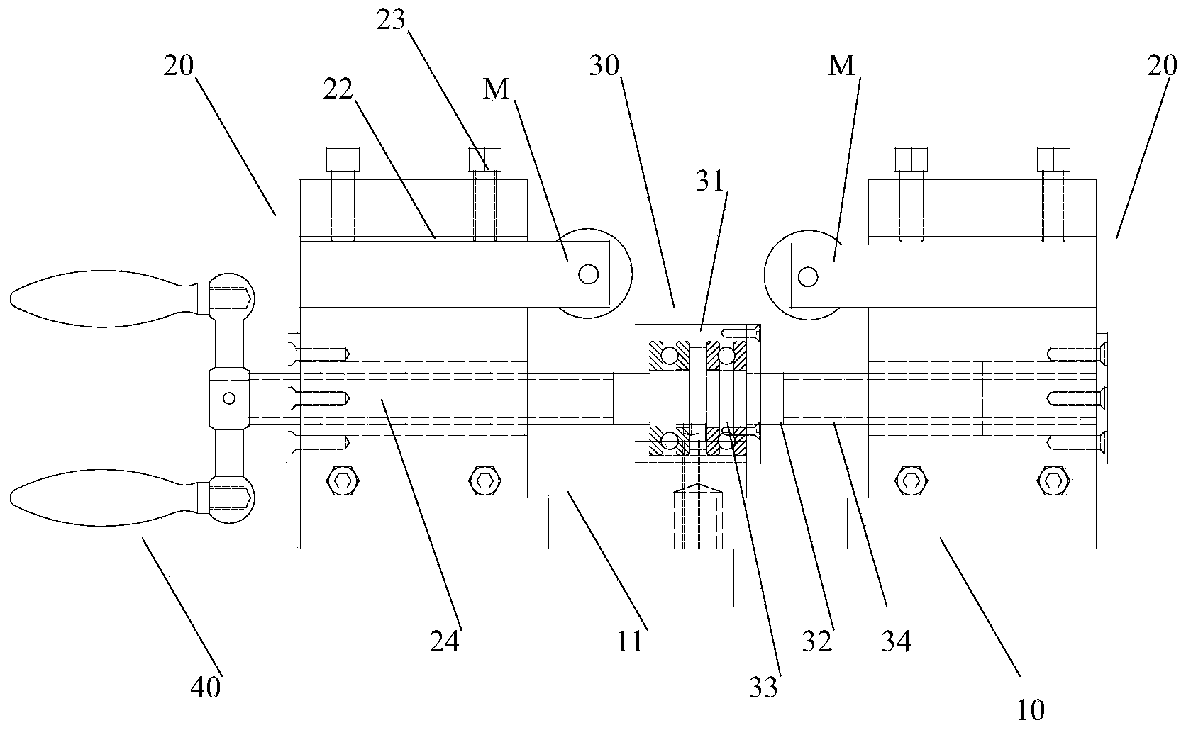
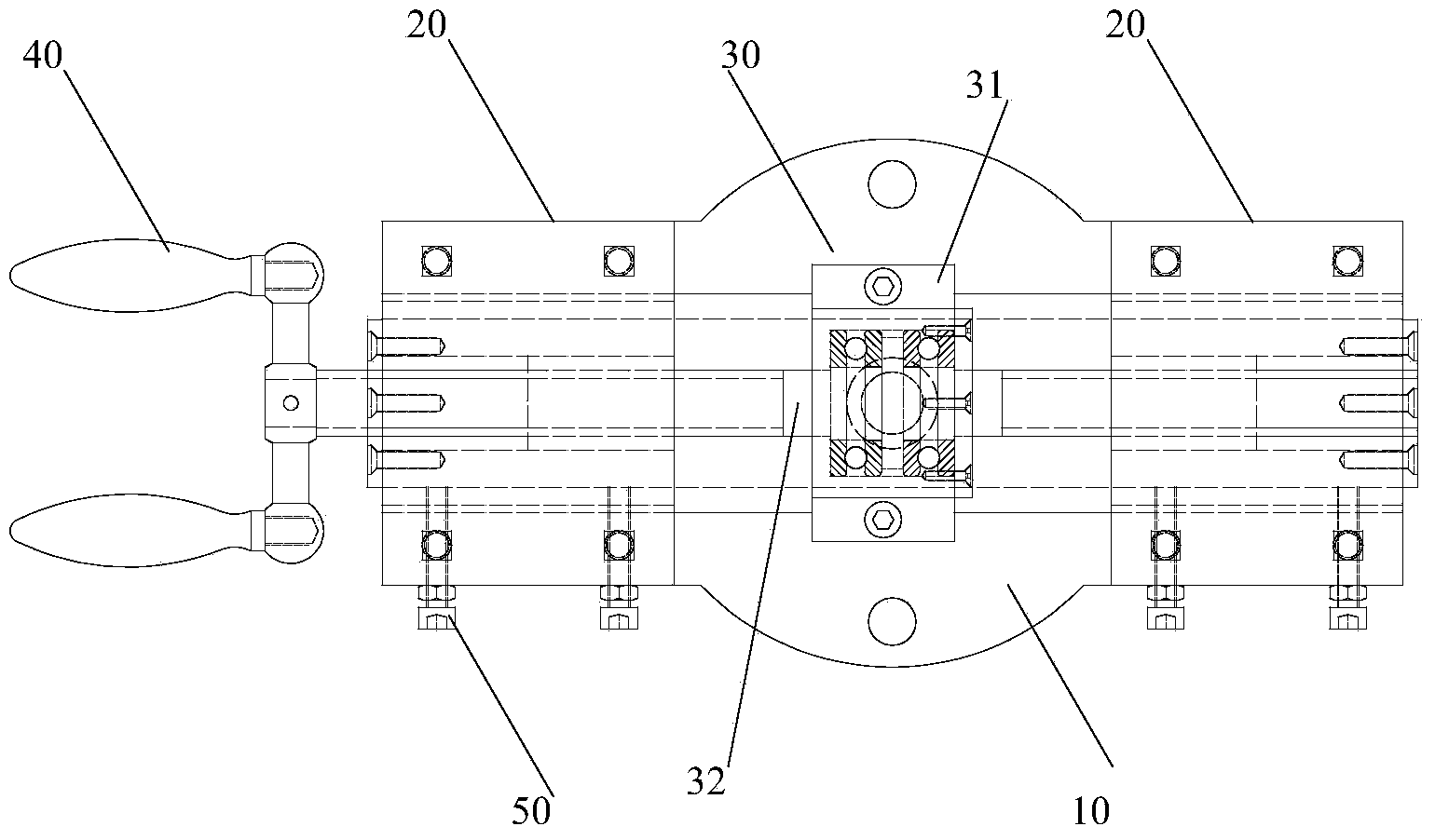
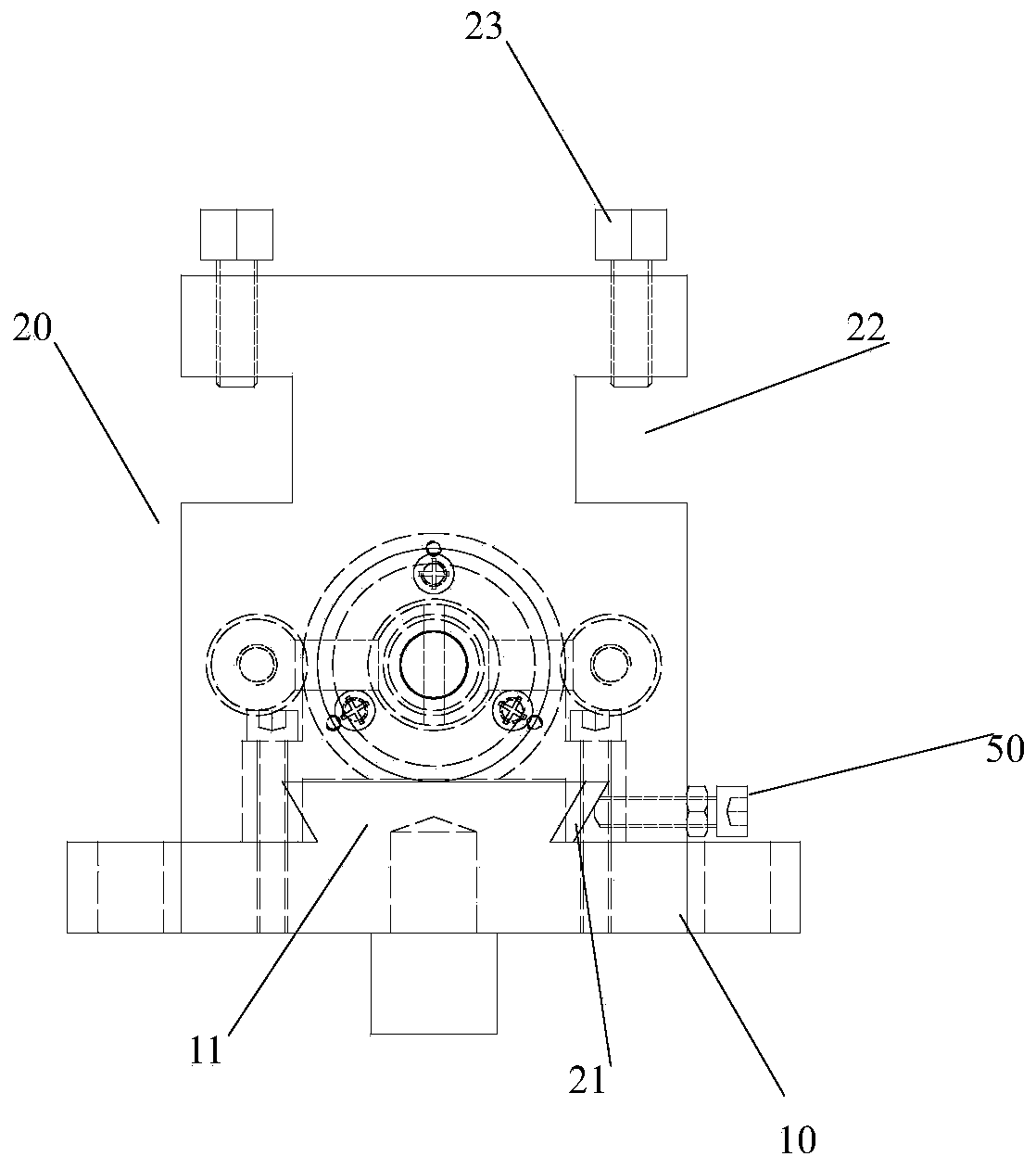
[0017] figure 1 It is a schematic front view showing the clamping device of the knurling tool of the present invention. figure 2 It is a schematic plan view showing the clamping device of the knurling tool of the present invention with the tool removed. image 3 It is a schematic side view showing the knurling tool clamping device of the present invention with the tool removed.

[0018] Such as Figure 1 to Figure 3 As shown, the knurling tool clamping device of the present invention has a base 10 with a guide rail 11 formed on the upper surface, two tool holders 20 , a guide member 30 and a rotating handle 40 .

[0019] The lower end of tool rest 20 is formed with the guide groove 21 that cooperates with guide rail 11, and the upper end of tool rest 20 is formed with tool clamping portion 22, and is formed with clamping member 23 on tool clamping ...


PUM


Abstract

The invention provides clamping equipment for knurling tools. The clamping equipment comprises a base, two tool carriers, a guide assembly and a rotary handle. A guide rail is formed on the upper surface of the base; guide grooves which are matched with the guide rail are formed in the lower ends of the two tool carriers, tool clamping portions are formed at the upper ends of the tool carriers, clamping assemblies are formed on the tool clamping portions, the tools can be clamped on the tool clamping portions by the aid of the clamping assemblies, and internally threaded holes which are perforated through the tool carriers are formed in the middles of the tool carriers along the extending directions of the guide grooves; the guide assembly comprises a fixing block and a guide shaft, the guide shaft extends along the guide rail and is connected with the tool carriers, the fixing block is fixed to the middle of the guide rail along the length direction of the guide rail in a crossing manner, the middle of the guide shaft in the length direction of the guide shaft is connected with the fixing block by bearings, externally threaded portions which can be matched with the internally threaded holes of the tool carriers are formed on two sides of the guide shaft, the two sides of the guide shaft are centered around the fixing block, and the turning directions of threads of the two externally threaded portions are opposite to each other; the rotary handle is connected with one end of the guide shaft of the guide assembly, so that the guide shaft can rotate under the effect of the rotary handle.

Description

technical field [0001] The invention relates to a clamping device, in particular to a clamping device for a knurling tool. Background technique [0002] At present, according to the requirements of users, a plurality of small grooves along the axial direction are formed at intervals on the circumferential surface of the end of the small shaft, that is, one end of the small shaft needs to be knurled to form a gear shape. . Currently, the end of the small shaft to be knurled is clamped by a pair of gear-shaped hobs, the other end of the small shaft is clamped by a chuck, and then the chuck is driven to rotate to rotate the small shaft around its axis to pass through the hob. The knives form small grooves at the end of the small shaft, from which knurling is performed. [0003] However, in the prior art, the tool holders for clamping the hob are arranged on both sides of the machine tool. When knurling is performed, the tool holders need to be driven separately to bring the h...

Claims


Application Information

Patent Timeline
Patent Type & Authority Applications(China)
IPC IPC(8): B23P9/02B23Q3/00
CPCB23P9/02B23Q3/00
Inventor 杜辰张钧王文春安明
Owner 天津市中马骏腾精密机械制造有限公司
Why Eureka
Try Eureka