
Cable-supported grid stadium steel roof structure

A technology for grid stadiums and steel roofs, which is applied to gymnasiums, roofs, building components, etc., and can solve the problems of difficult adjustment of steel roof cornice deformation, difficult construction operations, and lack of adjustability

Pending Publication Date: 2021-08-20
JINCHEN GROUP
View PDF1 Cites 0 Cited by
  • Summary
  • Abstract
  • Description
  • Claims
  • Application Information

AI Technical Summary

Problems solved by technology

For example, the publication number CN111424822A relates to a support-free construction method of a ring-shaped large cantilever cable-supported grid structure, including firstly carrying out structural installation on the periphery of the steel structure, then laying ring cables, and installing ring cable clamps; and then completing the installation of radial cables Laying and installation: Lay and install the support frame first, then complete the steel structure installation of the upper inner roof steel structure, upper outer roof steel structure and ring beam; then install the upper inner stay cables, upper outer stay cables and upper bottom stay cables ; Realize the connection between the radial cable and the ring cable clamp and the strut; then the structure is formed by the overall tensioning and tensioning of the radial cable until the outer ring tire frame is detached, and then the installation of the inner diagonal brace is completed, and then the upper inner diagonal is disassembled Stay cables, upper outer stay cables and upper bottom stay cables; finally complete the roof, bridleway, etc., and complete the construction of the overall structure, which solves the problem of downward deformation at the front end of the roof. It is directly welded with cast steel ear plates, lacks adjustability, and the construction process has problems such as difficulty in adjusting deformation of steel roof eaves with flexible structure, additional construction stress affecting safety, difficult construction operation and high construction cost

Method used


Image

  • Cable-supported grid stadium steel roof structure
  • Cable-supported grid stadium steel roof structure
  • Cable-supported grid stadium steel roof structure

Examples


Embodiment 2

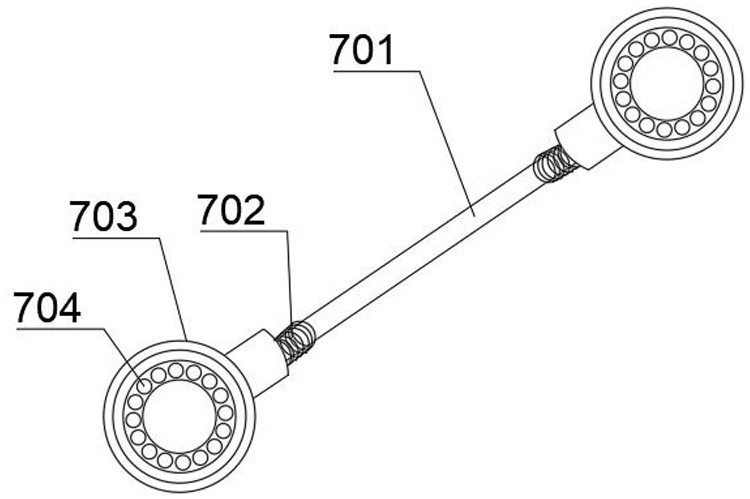
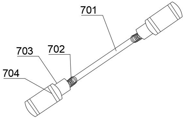
[0034] Others are consistent with the scheme of Embodiment 1, the rod 701 is a steel pipe column, the diameter of the steel pipe column is 180-200mm, and the wall thickness of the steel pipe column is 8-10mm.

Embodiment 3

[0036] The rest are consistent with the solution of Embodiment 1 or 2, and the adjustment range of the stroke of the adjustment screw assembly 702 is 0-60 mm.

Embodiment 4

[0038] The rest are consistent with any one of the embodiments 1-3, and the angle adjustment range of the ball hinge ear piece 703 is 0-15 degrees.


PUM


Abstract

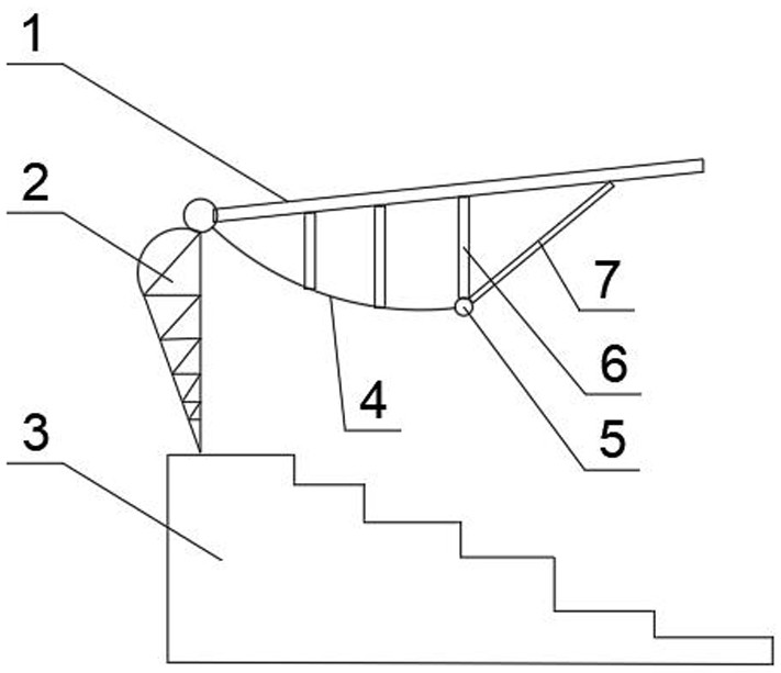
The invention discloses a cable-supported grid stadium steel roof structure. The cable-supported grid stadium steel roof structure comprises a grid steel structure (1), truss supporting columns (2), a concrete stand (3), radial steel cables (4), annular steel cables (5), vertical supporting rods (6) and inclined supporting rods (7), and each inclined supporting rod comprises a rod piece (701), adjusting thread assemblies (702) arranged at the two ends of the rod piece and angle adjusting assemblies arranged at the two ends of the rod piece; and the inclined supporting rods are hinged to the cast steel joints of the radial steel cables and the annular steel cables and the grid steel structure (1) through the adjusting thread assemblies, and the angle adjusting assemblies comprise spherical hinge lug pieces (703) and needle bearings (704) matched with the spherical hinge lug pieces. The functions of adjustable length and automatic angle adjustment of the inclined supporting rods are achieved, and the problems that in the prior art, deformation of a steel roof cornice is difficult to adjust, safety is affected by construction additional stress, construction operation is difficult, and the construction cost is high are solved.

Description

technical field [0001] The invention relates to the technical field of stadium steel structure installation, in particular to a steel roof structure of a cable-supported grid stadium. Background technique [0002] With the development of the stadium steel structure support system, the cable-supported grid steel structure has been widely used because of its remarkable mechanical characteristics. But for the cable-supported grid steel structure of the stadium, the cornice deformation of the cantilevered steel roof is difficult to control. The key to the construction of cable-supported grid steel structure is to maintain the coordination of "force" and "shape" among tension cables, struts and grid steel structure. By tensioning the radial cables, the hoop cables and struts are tightened, and the diagonal struts connected to the cornice of the steel roof are the key components to adjust the adaptation of "force" and "shape". [0003] Under the existing technical conditions, th...

Claims


Application Information

Patent Timeline
Patent Type & Authority Applications(China)
IPC IPC(8): E04B7/00E04H3/14
CPCE04B7/00E04H3/14
Inventor 蒋凤昌唐金来黄光辉郁俊周桂香林网朋移伯华冯宁馨鞠嘉伟
Owner JINCHEN GROUP
Learn More