Method of producing autoclaved aerated concrete members by cutting blanks with meshed wires
A technology of autoclaved aeration and concrete, applied in the direction of manufacturing tools, ceramic molding machines, etc., can solve the problems affecting the accuracy of horizontal cutting surfaces, and achieve the effects of saving construction hours, simplifying masonry construction, and saving raw materials
- Summary
- Abstract
- Description
- Claims
- Application Information
AI Technical Summary
Problems solved by technology
Method used
Image
Examples
Embodiment 1
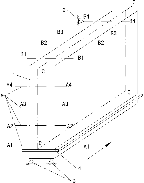
[0036] Such as Figure 1 to Figure 5 , cutting and making blocks with a general precision level of 300 mm in length, eliminating most of the mechanical cutting processing when building walls with staggered joints.
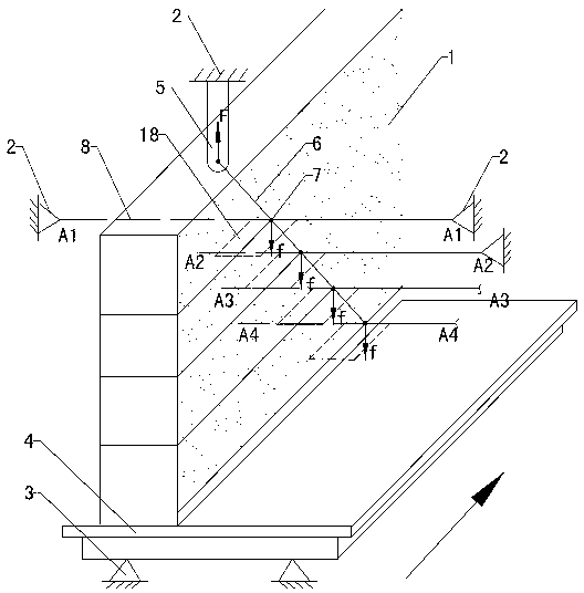
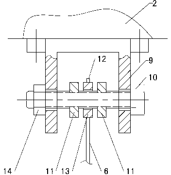
[0037] join figure 1 The embryo body 1 that can be cut to form a component passes through the embryo body carrying plate 4 and stops statically on the embryo body holding platform 3, and the AA direction steel wire 8 for horizontal plane cutting is completed, and the BB direction steel wire for vertical plane cutting perpendicular to the longitudinal direction is completed according to the masonry The size of the block is required to be installed on the cutting machine; use a CC-directed steel wire 6 on the vertical plane CC parallel to the longitudinal direction to cut the embryo body 1 into two parts, and the length of the component is 300 mm. The CC direction steel wire 6 adopts 1.0 mm spring steel wire, and the upper end is fixed on the cutting machine 2 above...
Embodiment 2
[0042] An example of two CC-directed steel wires 6 completing two CC face cuts, see Figure 7 . Two CC direction steel wires 6 are installed with reference to Example 1, one is aligned with the center plane of the embryo body 1, and the distance between the two CC direction steel wires 6 is 150 mm. Blocks with a height of 300 mm and 150 mm can be cut.
Embodiment 3
[0044] According to GB11968-2006 "Autoclaved Aerated Concrete Blocks" high-quality precision index, 300 mm long blocks are produced. The height dimension is 300 mm, and the cutting layout of the embryo body is to cut horizontally into 4 layers, and one CC is set to steel wire 6. according to Figure 8 , set 4 sections of zigzag CC direction steel wires 6 . The inclination angle of the broken line is 45°. Referring to Embodiment 1, the installation of the upper end fixing component 5, the connection points of the CC direction steel wire 6 and the AA direction steel wire 8 is completed. refer to Figure 7 , complete the installation of the stabilizer rudder 17. Stabilizer 17 is made of semi-rigid stainless steel sheet with a thickness of 0.3 mm, a height of 4 mm, and downward; a width of 40 mm and a length of 305 mm; 4 A 4 The inclination is consistent; the stabilized rudder 17 and the CC direction steel wire 6 are welded by argon arc welding, and the welding spots are eve...
PUM
| Property | Measurement | Unit |
|---|---|---|
| Diameter | aaaaa | aaaaa |
| Thickness | aaaaa | aaaaa |
Abstract
Description
Claims
Application Information
 - R&D
- Intellectual Property
- Life Sciences
- Materials
- Tech Scout
- Unparalleled Data Quality
- Higher Quality Content
- 60% Fewer Hallucinations
Browse by: Latest US Patents, China's latest patents, Technical Efficacy Thesaurus, Application Domain, Technology Topic, Popular Technical Reports.
© 2025 PatSnap. All rights reserved.Legal|Privacy policy|Modern Slavery Act Transparency Statement|Sitemap|About US| Contact US: help@patsnap.com


