Smart antenna

An intelligent, antenna technology, applied in the direction of antennas, electrical components, etc., can solve problems such as no obvious help, antenna design location restrictions, etc.

Inactive Publication Date: 2007-06-13
ALPHA NETWORKS INC
View PDF0 Cites 9 Cited by
  • Summary
  • Abstract
  • Description
  • Claims
  • Application Information

AI Technical Summary

Problems solved by technology

[0003] When designing wireless transceivers in the industry, there has been a trend of increasingly miniaturized, resulting in smaller and smaller positions for the circuit boards inside the wireless transceivers to be provided with the antennas. In addition, the interior of the wireless transceivers The requirements of various parts and mechanisms cause the design position of the antenna inside the wireless transceiver device to be subject to many restrictions, resulting in the distance between the antennas of the circuit board getting closer and closer, so that the antenna can use the antenna After the diversity multitasking (Antenna Diversity) technology, it has not really achieved the purpose of the best information sending and receiving quality
[0004] In order to specifically illustrate the reasons why the antennas on the circuit board cannot achieve the purpose of achieving the best quality of information transmission and reception, an example is given to illustrate it. Please refer to Figure 1. There are two antenna units on the circuit board 1. The two antenna units 1 are respectively connected to a first connection terminal 20 provided on one side of

Method used


Image

  • Smart antenna
  • Smart antenna
  • Smart antenna

Examples


Embodiment Construction

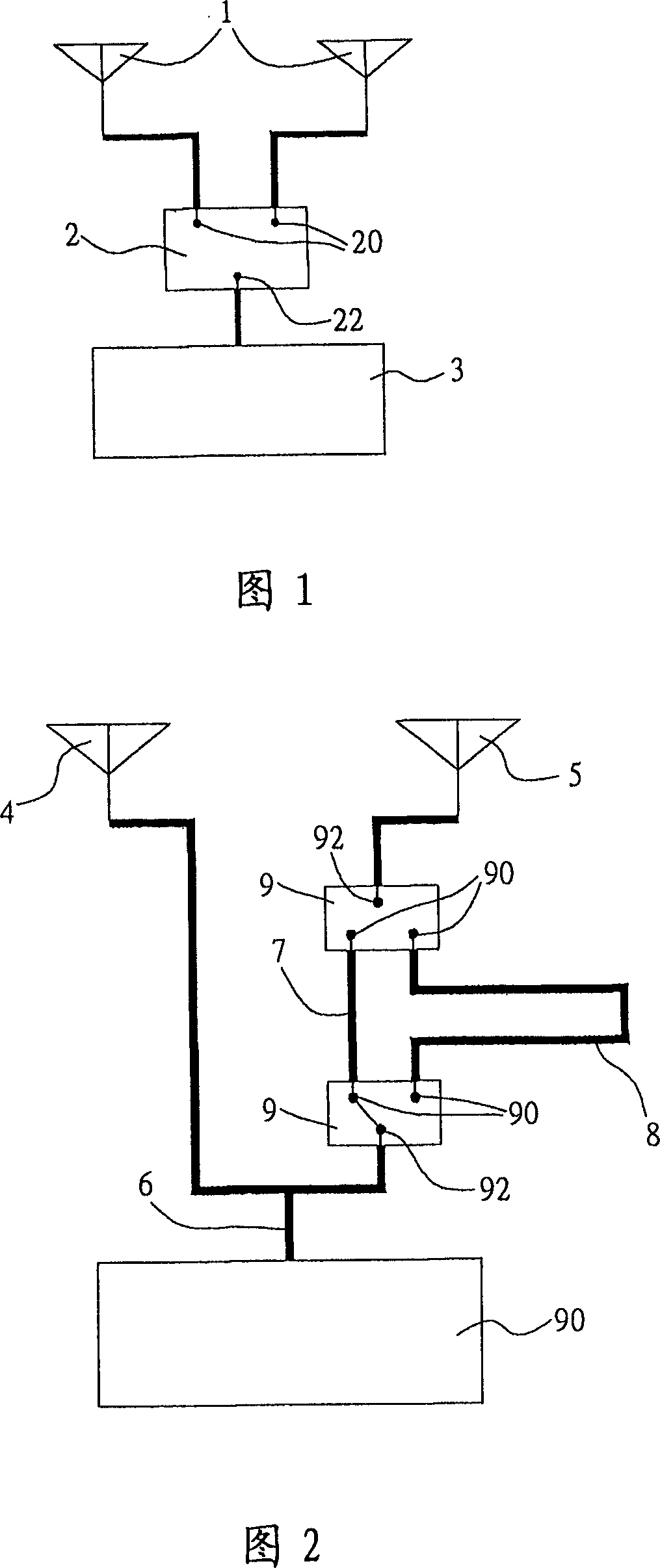
[0019] The present invention is a kind of smart antenna, please refer to Fig. 2, comprise a first antenna unit 4, a second antenna unit 5, a T-shaped connector 6, a first transmission line 7 arranged on a circuit board , a second transmission line 8 and two radio frequency switches 9, wherein each of the antenna units 4, 5 is connected to two symmetrical ends of the T-shaped connector 6, so that the two antenna units 4, 5 and the T-shaped connector 6 form a Antenna array (Two-Element Antenna Array), and an asymmetric end on the T-shaped connector 6 is used as a feed-in end of an antenna diversity multitasking transceiver circuit 94 set on the antenna array and the circuit board, the The feed-in end can feed information to the two antenna units 4, 5, and the two radio frequency switches 9 are arranged between the second antenna unit 5 and the T-shaped connector 6, and the two transmission lines 7, 8 are arranged on Between the two radio frequency switchers 9, the antenna divers...


PUM


Abstract

The intelligence type antenna is an antenna array composed of two antenna units and T type connector. Two radio frequency switchers are setup between one antenna unit and T type connector. There are two transmission lines between two radio frequency switchers. After two radio frequency switchers are switched, through first transmission line or second transmission line, the antenna units connected to the radio frequency switcher are connected to the T type connector so as to make information fed to the two antenna units generate difference between in-phase or out-of-phase. Thus, two antenna units are utilized at same time. Comparing with traditional antenna diversity multitasking, the invention solves disadvantages that only one antenna is utilized at same time. The invention can receive information in optimal quality.

Description

technical field [0001] The present invention relates to a smart antenna, especially to an antenna array that uses a T-shaped connector to form two antenna units, and a two-radio frequency switcher is arranged between one of the antennas and the T-shaped connector, and the two radio-frequency switches Two transmission lines are arranged between the devices, so that the two antenna units are used at the same time, and the best quality information can be received. Background technique [0002] Due to the current wireless local area network (WLAN) specifications, in order to prevent dead ends in the use of wireless transceiver devices, it is required that the wireless transceiver device must have multiple antennas (Antenna Diversity), and the antennas will use antenna diversity to multitask (Antenna Diversity) technology, in order to achieve the best quality of information transmission and reception. [0003] When designing wireless transceivers in the industry, there has been ...

Claims


Application Information

Patent Timeline
IPC IPC(8): H01Q3/00H01Q3/22H01Q3/30
Inventor 叶明豪
Owner ALPHA NETWORKS INC
Why Eureka
Try Eureka