
Electronic device with USB connector plug capable of turning and folding

A technology for connector plugs and electronic devices, applied in flexible/rotatable wire connectors, installation and connection of connecting parts, etc., can solve the problems of general products without structure, waste of length and space, and increase product cost, so as to achieve low cost, The effect of reducing the length space and preventing breakage

Inactive Publication Date: 2007-06-13
AIGO DIGITAL TECHNOLOGY CO LTD
View PDF1 Cites 16 Cited by
  • Summary
  • Abstract
  • Description
  • Claims
  • Application Information

AI Technical Summary

Problems solved by technology

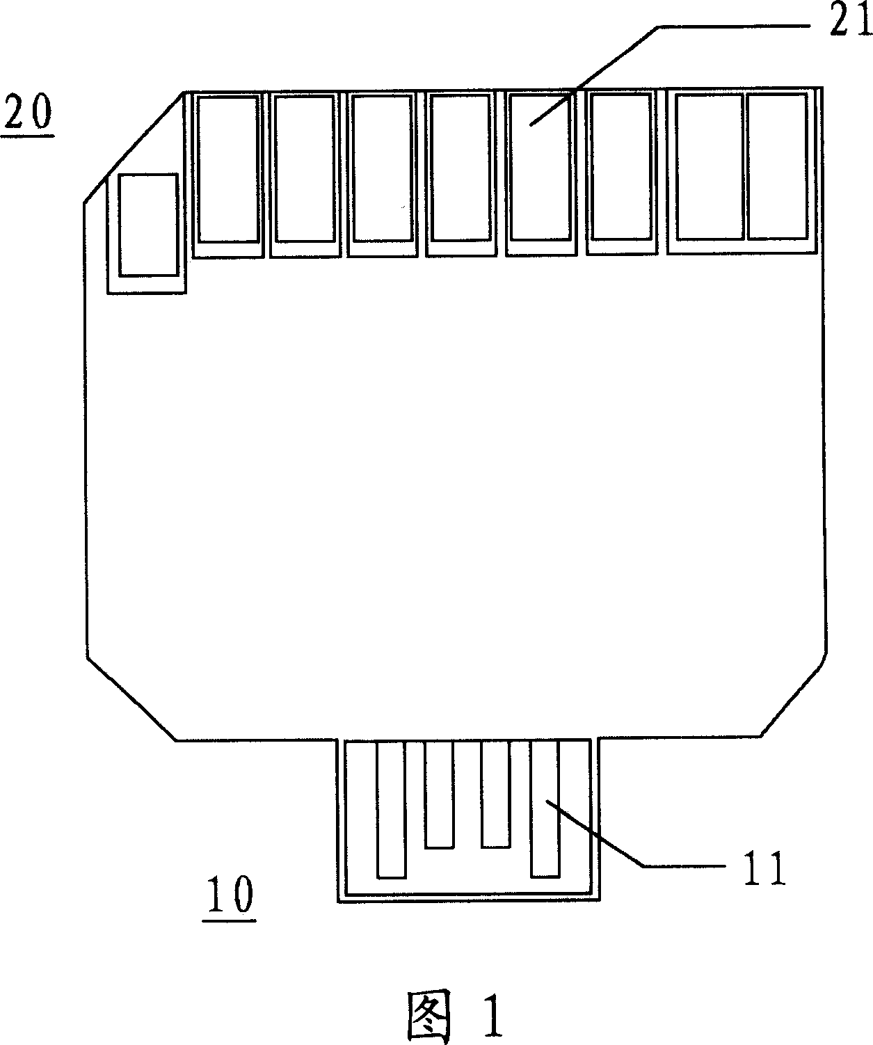
However, the product with the above-mentioned structure also has the disadvantages of being easy to wear and tear, and wastes length and space. Moreover, when the USB interface socket is inserted, the rear part of the USB plug protrudes to the outside, so it is not only easy to break, but also Cannot be used when the length of the space outside the socket is short
At the same time, because the structure shown in Figure 1 must form idle spaces on both sides of the USB connector so that the connector can be inserted into the socket, but this design must increase the integration of parts other than the connector, thereby increasing the product cost
[0005] This shows that above-mentioned existing electronic device with USB connector plug obviously still has inconvenience and defect in structure and use, and urgently needs to be further improved
In order to solve the problems existing in electronic devices with USB connector plugs, relevant manufacturers have tried their best to find a solution, but no suitable design has been developed for a long time, and there is no suitable structure for general products to solve The above-mentioned problems are obviously the problems that relevant industry players are eager to solve

Method used


Image

  • Electronic device with USB connector plug capable of turning and folding
  • Electronic device with USB connector plug capable of turning and folding
  • Electronic device with USB connector plug capable of turning and folding

Examples


Embodiment Construction

[0043] In order to further explain the technical means and effects of the present invention to achieve the intended purpose of the invention, below in conjunction with the accompanying drawings and preferred embodiments, the electronic device with a foldable USB connector plug proposed according to the present invention is specifically implemented. Mode, structure, feature and effect thereof are as follows in detail.

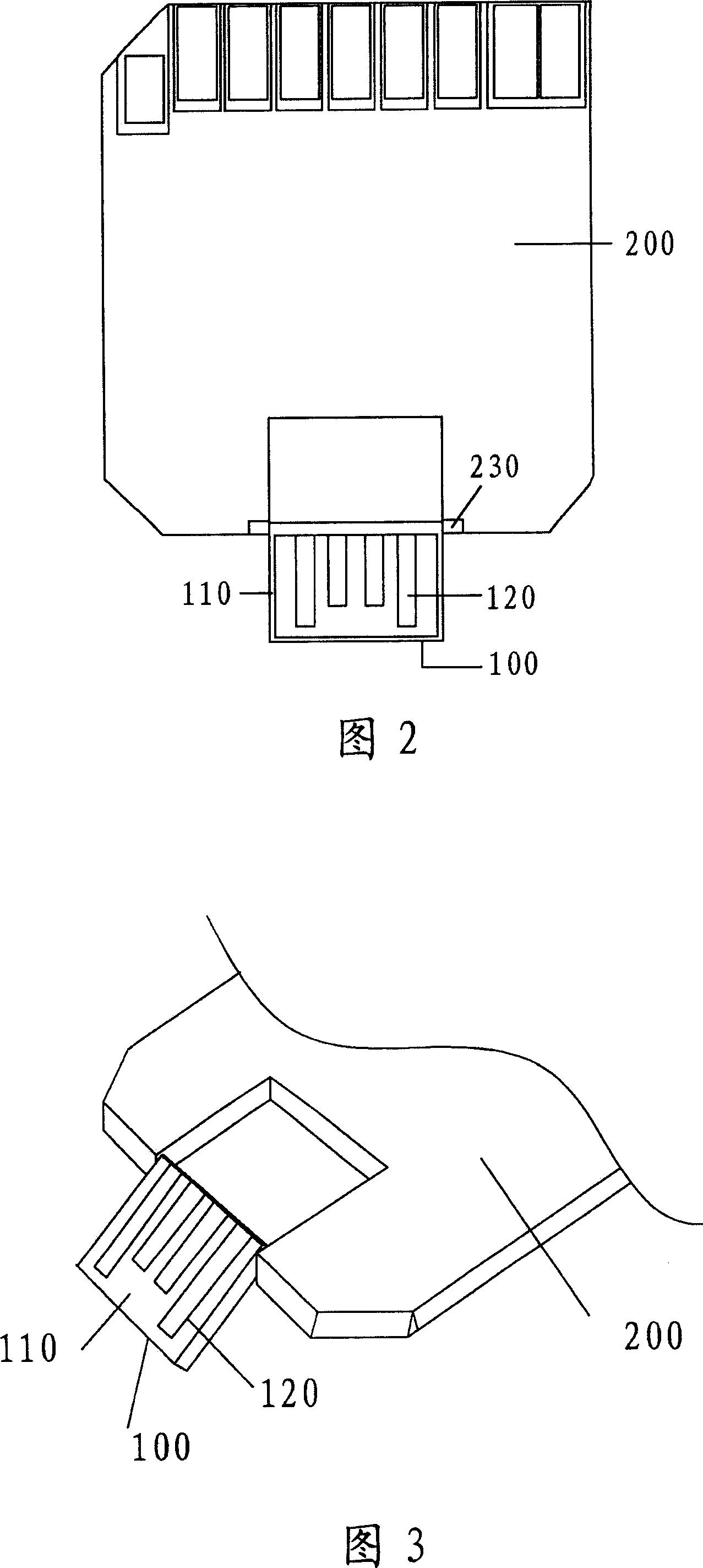
[0044] Please refer to Fig. 2 and Fig. 3, Fig. 2 is a schematic front view of a memory card with a foldable USB interface connection device of the present invention, and Fig. 3 is a schematic diagram of a three-dimensional structure of the USB interface connection device of the present invention in a folded state , the foldable USB connector plug 100 of the present invention can be set on a memory or memory card, connected with the electronic device end body 200 , and can rotate relative to the electronic device end body 200 .

[0045] Specifically, the part of ...


PUM


Abstract

The plug of USB connector includes following parts: main body of the plug includes two coaxial pin-connected bulges setup at two ends at top part, and through the said pin-connected bulges, the plug can be turned out from electronic device and inserted to USB socket; metal terminal set, one end of the set setup on external surface of the main body of the plug is connected to electric terminals of USB socket electrically when in state of inserting to USB socket; and the other end is connected to print circuit board setup on main body of electronic device. Depressed part on device is in use for accommodating plug of USB connector. Being setup on top of two walls, the taking up parts are corresponding to the pin-connected bulges for their connection. Advantages are: anti abrasion, preventing break, easy of carrying, reducing integrity of product, and convenient for use at narrow space.

Description

technical field [0001] The present invention relates to an electronic device with a foldable connector plug for a Universal Serial Bus (USB) interface, in particular to an electronic device with a low-thickness foldable USB connector plug, and the plug is It can be flipped out and inserted into the USB interface, and can be retracted and used as a standard memory card (such as MMC card, SD card, etc.). Background technique [0002] Existing universal serial bus (USB) interface connector has become a kind of technical standard, but because the existing standard USB plug has shell, caused it to occupy a larger space, so should the needs of actual production and life, existing Technology has proposed an improved USB connector plug. [0003] The above-mentioned improved USB connector plug, as disclosed by the State Intellectual Property Office of China on August 20, 2003, has an application number of 02103174.6 and an invention patent titled "Low Thickness Connecting Device for...

Claims


Application Information

Patent Timeline
IPC IPC(8): H01R13/73G06K7/00
CPCH01R35/04
Inventor 曹镇
Owner AIGO DIGITAL TECHNOLOGY CO LTD
Learn More