Wire cutting device for swwing machine

A sewing machine and thread cutting technology, which is applied to sewing machine components, thread cutting mechanisms in sewing machines, sewing equipment and other directions, can solve problems such as large driving force, and achieve the effects of improving reliability, realizing miniaturization, and preventing poor action.

Inactive Publication Date: 2007-06-20
JUKI CORP
View PDF1 Cites 5 Cited by
  • Summary
  • Abstract
  • Description
  • Claims
  • Application Information

AI Technical Summary

Problems solved by technology

[0009] However, when the pressing force is set high, since the frictional force between the two is increased, a large driving force is required when the movable cutter moves forward and backward, especially when it is start

Method used


Image

  • Wire cutting device for swwing machine
  • Wire cutting device for swwing machine
  • Wire cutting device for swwing machine

Examples


Embodiment Construction

[0034] (overall structure of the embodiment)

[0035] Hereinafter, the thread cutting device 100 (hereinafter, simply referred to as the thread cutting device 100 ) of the sewing machine according to the embodiment of the present invention will be described in detail with reference to FIGS. 1 to 12 .

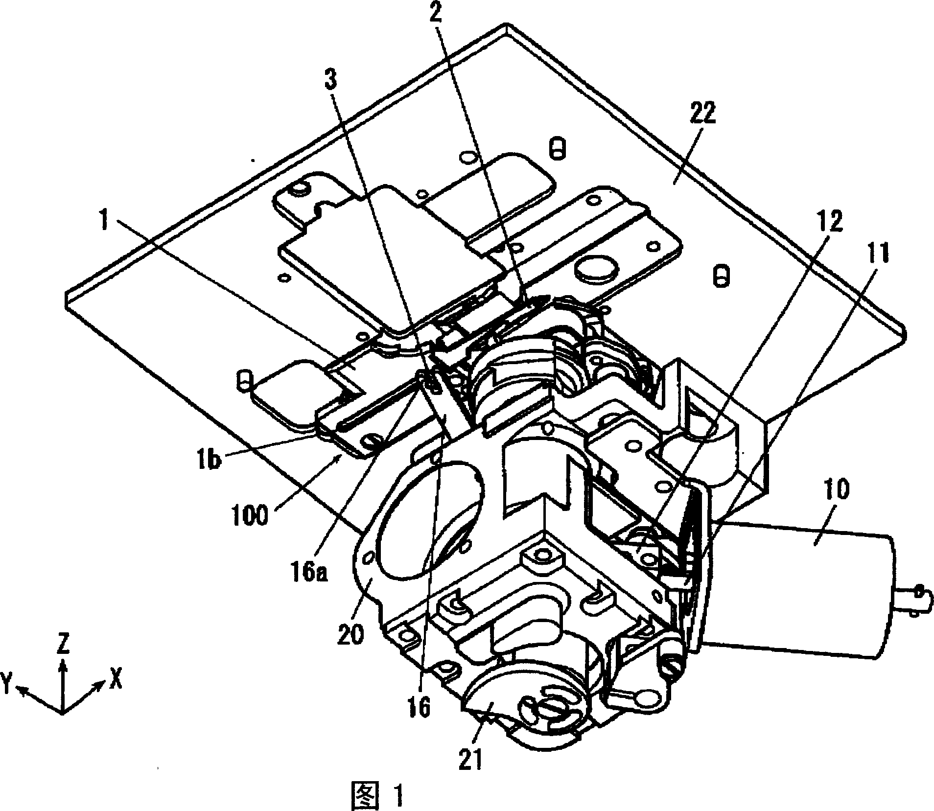
[0036] As shown in FIG. 1 , the thread cutting device 100 according to the present embodiment is mounted on the lower surface of the needle plate 22 disposed near the needle drop position along the upper surface of the sewing machine floor (not shown).

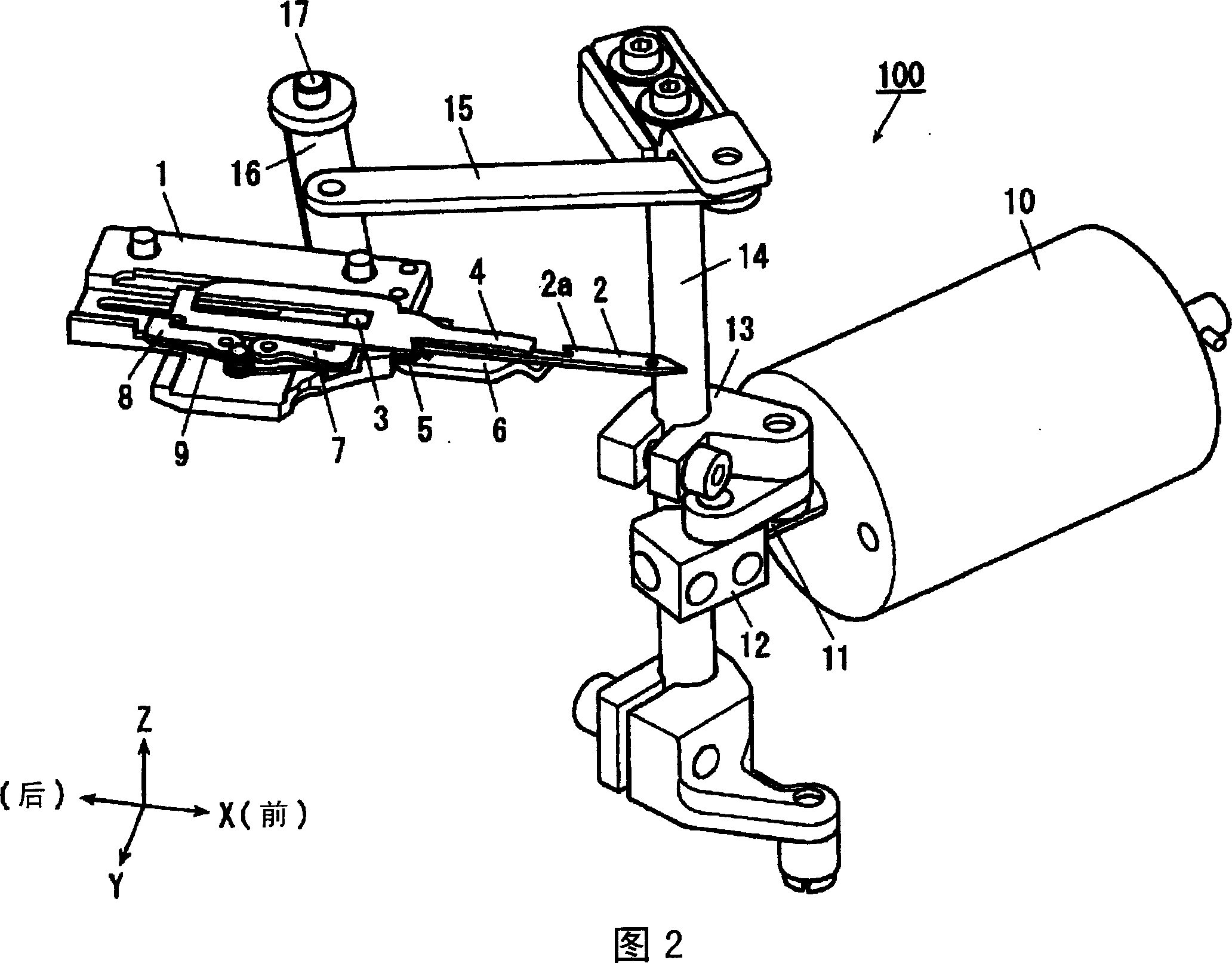
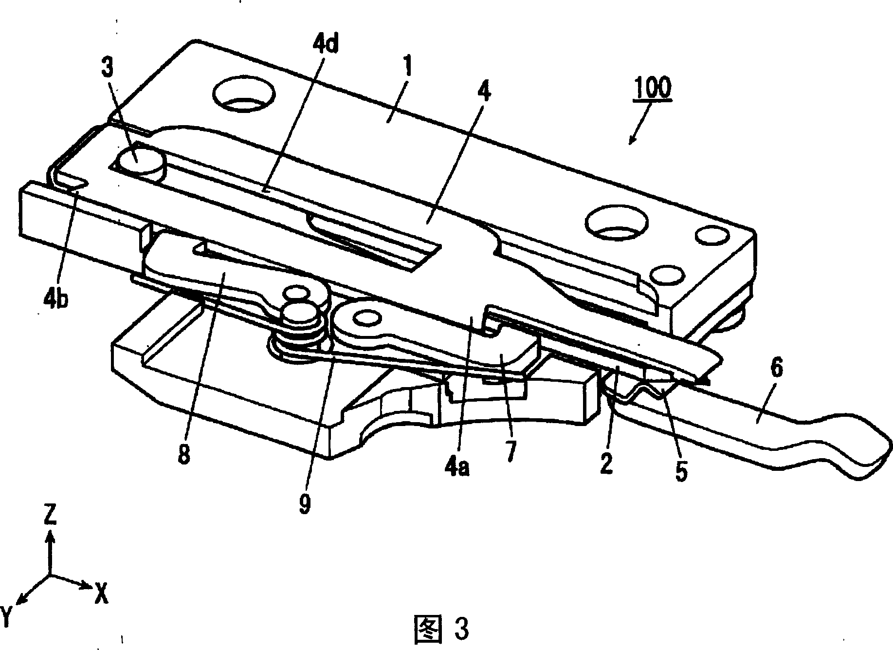
[0037] As shown in FIG. 2 , the thread cutting device 100 has: a movable cutter 2 that reciprocates between a standby position and a thread catching position; The fixed knife 4 that moves back and forth and cooperates with the movable knife 2 to cut the sewing thread at the active position, the front stopper 7 that keeps the fixed knife 4 at the standby position, and keeps the fixed knife 4 in the active position. position of t...


PUM


Abstract

Thread separation device of the invention comprises: a mobile knife 2 moving between a ready position and a thread catch position back and forth; a being certain thing knife 4 moving between a ready position and a working position back and forth and separating a thread in cooperating with the mobile measurer 2 in the working position, a front stopper 7 holding the being certain knife 4 in the ready position ; a rear stopper 8 holding the being certain knife 4 in the working position; a thread retaining spring 5, linking up the mobile knife 2 to the side of the being certain measurer 4; a measurer pressure adjustment plate 6, linking up the mobile knife 2 to the side of the being certain measurer 4 in a larger force for linking up than that of the thread retaining spring 5; a measurer basis 1 for holding each of these members; and thread separation electromagnets 10 as a power source for driving the mobile knife 2. The measurer pressure adjustment plate 6 has a pattern to link up the mobile knife 2 to the side of the being certain measurer 4 in a working position without linking up in a ready position.

Description

technical field [0001] The present invention relates to a thread cutting device of a sewing machine having a movable knife having a catch portion for catching a sewing thread and a fixed knife cutting the sewing thread by slidingly contacting the movable knife. Background technique [0002] Conventionally, there is known a thread cutting device for a sewing machine: it is provided in the bottom plate of the sewing machine, and has a movable cutter that moves forward and backward near the needle drop position after sewing and a fixed cutter that engages with the movable cutter (for example, Refer to Patent Document 1). [0003] The movable cutter has a catching part that catches the upper thread and the lower thread when moving backward after moving forward near the needle drop position. And, while drawing the upper thread and the lower thread caught by the catcher, these sewing threads are cut by cooperating with the fixed cutter. [0004] In addition, the fixed knife adop...

Claims


Application Information

Patent Timeline
IPC IPC(8): D05B65/00
CPCD05B65/02
Inventor 吉田文彦坂本真一
Owner JUKI CORP
Why Eureka
Try Eureka