Centrifugal pump

A centrifugal pump and pump body technology, applied in the direction of pumps, driving pumps, pump components, etc., can solve the problems of inconvenient installation, maintenance, maintenance, complicated configuration, etc., and achieve the effect of simple structure, low manufacturing cost and improving pump efficiency.

Active Publication Date: 2007-06-20
天津港保税区鑫利达石油技术发展有限公司
View PDF3 Cites 5 Cited by
  • Summary
  • Abstract
  • Description
  • Claims
  • Application Information

AI Technical Summary

Problems solved by technology

[0007] The configuration of the known technical mechanism is complicated, which brings inconvenience to installation, inspection and maintenance

Method used


Image

  • Centrifugal pump

Examples


Embodiment Construction

[0029] Below in conjunction with preferred embodiments, the specific implementation, features and effects provided by the present invention are described in detail as follows; for the purpose of simplicity and clarity, the description of known technologies is appropriately omitted below to avoid unnecessary details Affect the description of this technical solution.

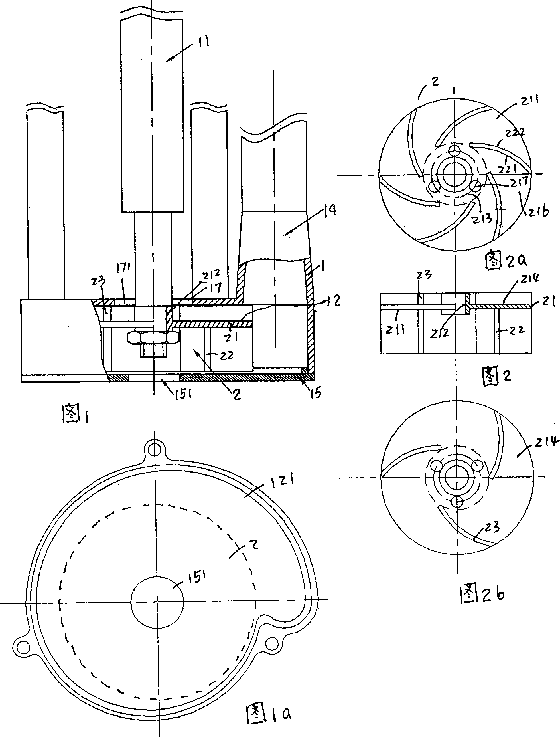
[0030] Referring to Fig. 1-2, a centrifugal pump includes a drive shaft 11 connected to a motor, an impeller 2 is installed on the drive shaft, and the impeller is installed in the pump body 1, wherein the impeller has a disc 21, and the center of the disc is Hub 212, the impeller is mounted on the drive shaft through the hub, and several main blades 22 of equal height and equal thickness are arranged on one side 211 of the disc. On the surface, the radius of curvature at the front of the blade and the radius of curvature at the back of the blade are drawn from the same center point;

[0031] The starting point o...


PUM


Abstract

A centrifugal pump comprises an impeller installed on the driving shaft. On one side of the impeller disk are disposed main vanes and on the other side of the disk are disposed secondary vanes. There is a preset distance from the starting point of the vane to the hub to form a traffic island area around the hub. A runner formed between vanes is in communication with the traffic island area with the traffic island area with spilling throughholes. The pump body has a chamber for holding vanes and the chamber has a curved channel with a water discharging tube. A liquid intake with an opening and closing mechanism is disposed in the centre of the pump head corresponding to the impeller.

Description

technical field [0001] The invention belongs to the technical field of submerged centrifugal pumps, in particular to a centrifugal pump for pumping gas-containing liquid. Background technique [0002] Mud pumps for drilling fluid generally run around the clock. When there is no mud (or liquid) coming out, the centrifugal pump will not stop. When mud (or liquid) comes in again, the centrifugal pump will not work properly due to gas accumulation in the center of the centrifugal pump impeller. Aspirate. To this end, the industry has made many efforts. [0003] Such as the published Chinese patent CN03211817.1 a water ring vacuum self-priming centrifugal pump, wherein the centrifugal pump part includes a centrifugal pump body and a centrifugal pump impeller installed on the pump shaft, the pump body is provided with a liquid inlet and outlet, the centrifugal pump A bearing body with a water ring chamber, a water ring vacuum chamber cover, a water ring vacuum impeller and a wat...

Claims


Application Information

Patent Timeline
Patent Type & Authority Applications(China)
IPC IPC(8): F04D9/02F04D29/24F04D29/42
Inventor 李明利
Owner 天津港保税区鑫利达石油技术发展有限公司
Why Eureka
Try Eureka