Multilayer inductor

A technology of stacking inductors and suppression layers, applied in the direction of inductors, fixed inductors, fixed signal inductors, etc., can solve the problem of inductance reduction, achieve the effect of preventing the reduction of inductance value and improving the DC superposition characteristics

Inactive Publication Date: 2007-06-20
TAIYO YUDEN KK
View PDF1 Cites 18 Cited by
  • Summary
  • Abstract
  • Description
  • Claims
  • Application Information

AI Technical Summary

Problems solved by technology

[0002] A closed magnetic circuit type multilayer inductor has a structure in which a plurality of conductor layers forming a coil are laminated with a magnetic layer interposed therebetween. However, when a DC current exceeding a predetermined value is applied, the inductance decreases due to magnetic saturation.

Method used


Image

  • Multilayer inductor
  • Multilayer inductor
  • Multilayer inductor

Examples


no. 1 Embodiment approach 〕

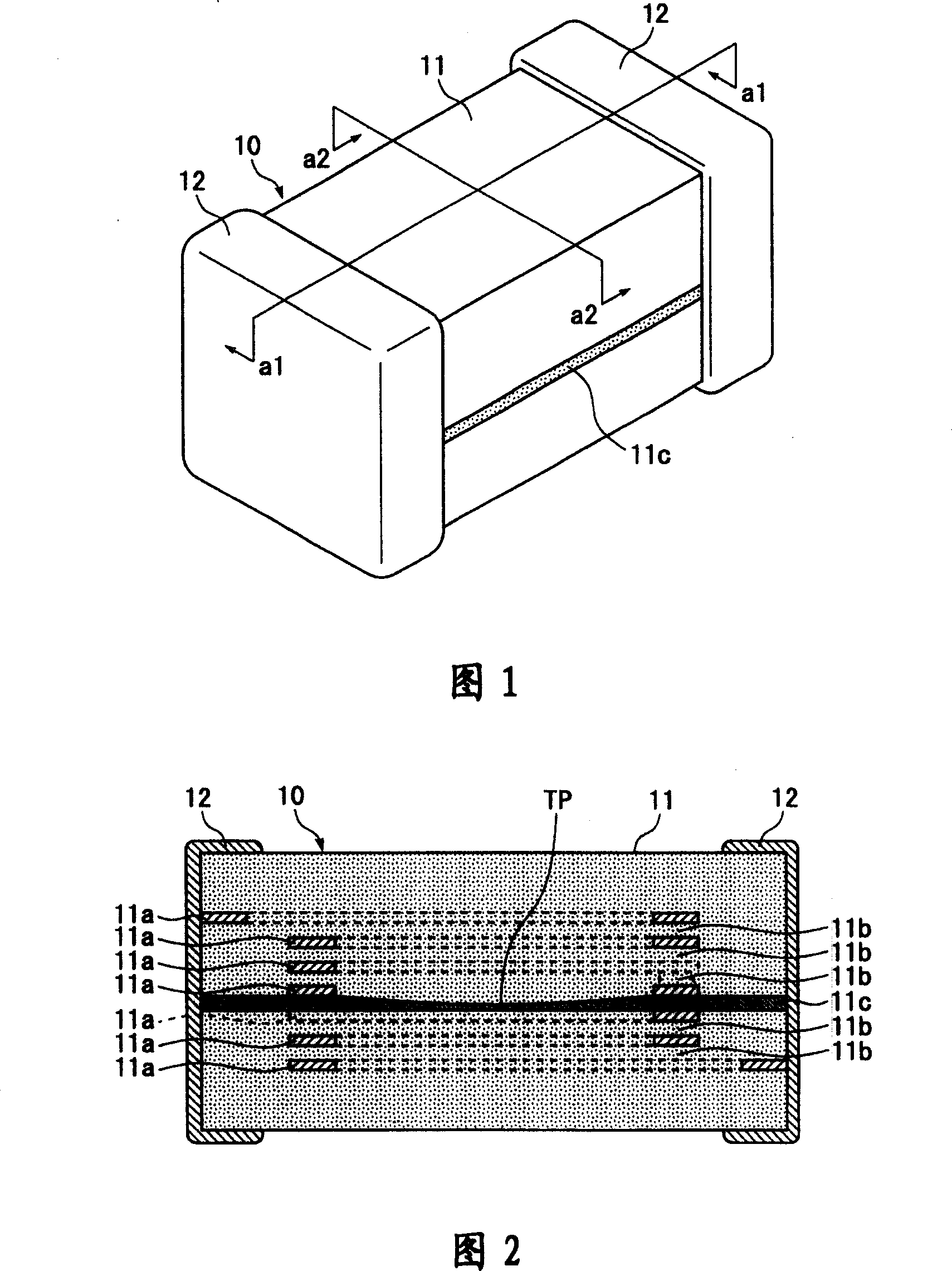
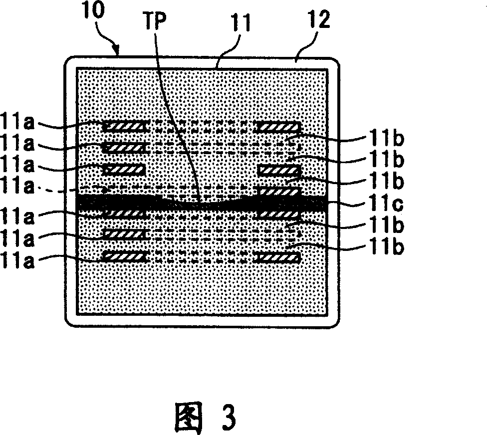
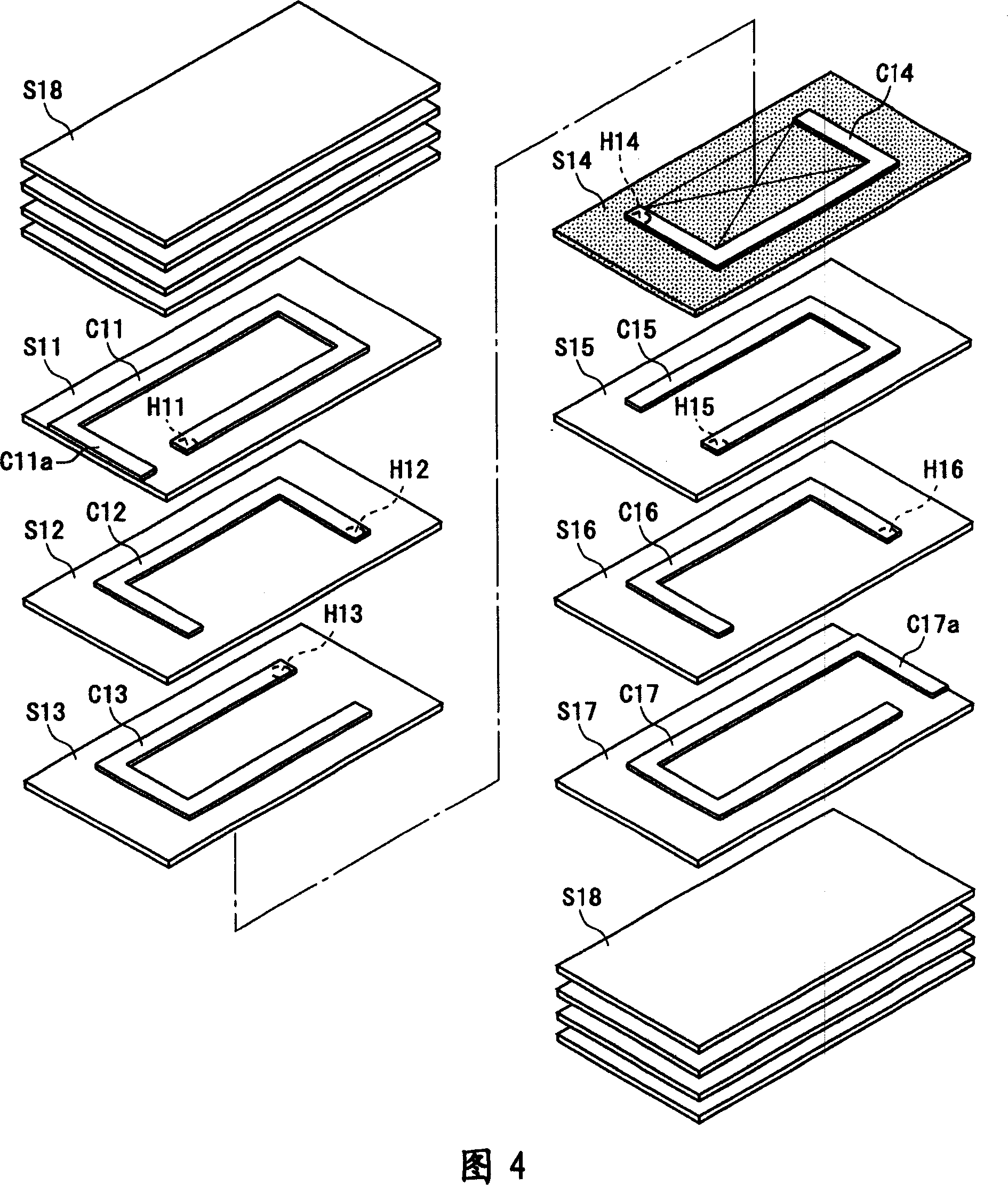
[0031] 1 to 11 show a first embodiment of the present invention. Fig. 1 is a perspective view of a laminated inductor, Fig. 2 is a sectional view taken along line a1-a1 in Fig. 1 , Fig. 3 is a sectional view taken along line a2-a2 in Fig. 1 , and Fig. 4 is an exploded perspective view of the laminated body shown in Fig. 1 , and Fig. 5 and 6 are partial perspective views and a 3-a3 line sectional view showing a part of the manufacturing steps of the multilayer inductor shown in FIG. 8 is a graph showing the inductance change rate of the multilayer inductor shown in FIG. 1, FIG. 9 and FIG. 10 are partial perspective views and a4-a4 line sectional views showing modified examples of the manufacturing steps, and FIG. 11 is another modification showing the manufacturing steps. Cutaway view of the example.

[0032] First, the structure of the multilayer inductor 10 will be described with reference to FIGS. 1 to 3 .

[0033] The multilayer inductor 10 includes a rectangular parallel...

no. 2 Embodiment approach 〕

[0061] 12 to 17 show a second embodiment of the present invention. Fig. 12 is a perspective view of a laminated inductor, Fig. 13 is a cross-sectional view taken along line b1-b1 in Fig. 12, Fig. 14 is a cross-sectional view taken along line b2-b2 in Fig. 12, and Fig. 15 is an exploded perspective view of the laminated body shown in Fig. 12, Fig. 16 and 17 are a partial perspective view and a b3-b3 sectional view showing a part of the manufacturing steps of the multilayer inductor shown in FIG. 12 . 18 and 19 are partial perspective views and b4-b4 line sectional views showing modified examples of manufacturing steps.

[0062] First, the configuration of the multilayer inductor 20 will be described with reference to FIGS. 12 to 14 .

[0063] The multilayer inductor 20 includes a rectangular parallelepiped multilayer body 21 , and external electrodes 22 , 22 provided on both ends of the multilayer body 21 in the longitudinal direction and made of a metal material such as Ag. ...


PUM

PropertyMeasurementUnit
thicknessaaaaaaaaaa
thicknessaaaaaaaaaa

Abstract

The present invention provides a multilayer inductor capable of improving DC superposition characteristics and preventing a decrease in inductance value. The increase in magnetic flux density is suppressed by the magnetic flux pass suppression layer (11c) arranged so as to block the magnetic flux passing through the inside of the coil, so that magnetic saturation when a direct current is applied can be suppressed and the direct current superposition characteristic can be improved. Furthermore, by making the thickness of the coil central part where the magnetic flux passes through the suppressing layer (11c) thinner than the thickness of the conductor layer near part, it is possible to reduce the reluctance of the coil central part where the magnetic flux density is low, and prevent the inductance value from being affected by the reluctance. And lower.

Description

technical field [0001] This invention relates to stacked inductors. Background technique [0002] A closed magnetic circuit type multilayer inductor has a structure in which a plurality of conductor layers forming a coil are laminated with a magnetic layer interposed therebetween. However, when a DC current exceeding a predetermined value is applied, the inductance decreases due to magnetic saturation. This phenomenon can be improved by changing the closed magnetic circuit type multilayer inductor into an open magnetic circuit. Specifically, as shown in FIG. improved between the body layers 1b. Among them, 2 in FIG. 20 is a pair of external electrodes, and 1a is a plurality of conductor layers constituting the coil. [0003] [Patent Document 1] Japanese Patent Application Laid-Open No. 56-155516 Contents of the invention [0004] In the multilayer inductor of FIG. 20 in which a nonmagnetic insulating layer 1c is interposed between magnetic layers 1b, magnetic saturation...

Claims


Application Information

Patent Timeline
Patent Type & Authority Applications(China)
IPC IPC(8): H01F17/00
CPCH01F17/04H01F3/14
Inventor 野木谦一郎
Owner TAIYO YUDEN KK
Why Eureka
Try Eureka