Laminated Coil Components

A technology of stacking coils and components, applied in the direction of electrical components, inductors, printed inductors, etc., can solve the problems of reduced inductance, reduced inner diameter of coil 73, and reduced inner diameter of helical coil 73, so as to prevent the reduction of inductance , the effect of preventing the concentration of conductors and preventing stacking offset

Active Publication Date: 2012-02-01
MURATA MFG CO LTD
View PDF3 Cites 0 Cited by
  • Summary
  • Abstract
  • Description
  • Claims
  • Application Information

AI Technical Summary

Problems solved by technology

Therefore, there is a problem that the inner diameter of the helical coil 73 is reduced, and the inductance is reduced.
In addition, since the pads 74a to 74j and the via-hole conductors 76a to 76e overlap the coil conductors 73a to 73f in a plan view, there is also a problem that the pads 74a to 74j and the coil conductors 73a to 73f are overlapped in the crimping process after lamination. The through-hole conductors 76a-76e apply a large pressure, the pads 74a-74j and the via-hole conductors 76a-76e are crushed, the inner diameter of the coil 73 is further reduced, or the pads 74a-74j and the via-hole conductors 76a-76e are crushed. stress concentration, thereby reducing the inductance

Method used


Image

  • Laminated Coil Components
  • Laminated Coil Components
  • Laminated Coil Components

Examples


no. 1 Embodiment

[0036] (for the first embodiment, refer to figure 1 and figure 2 )

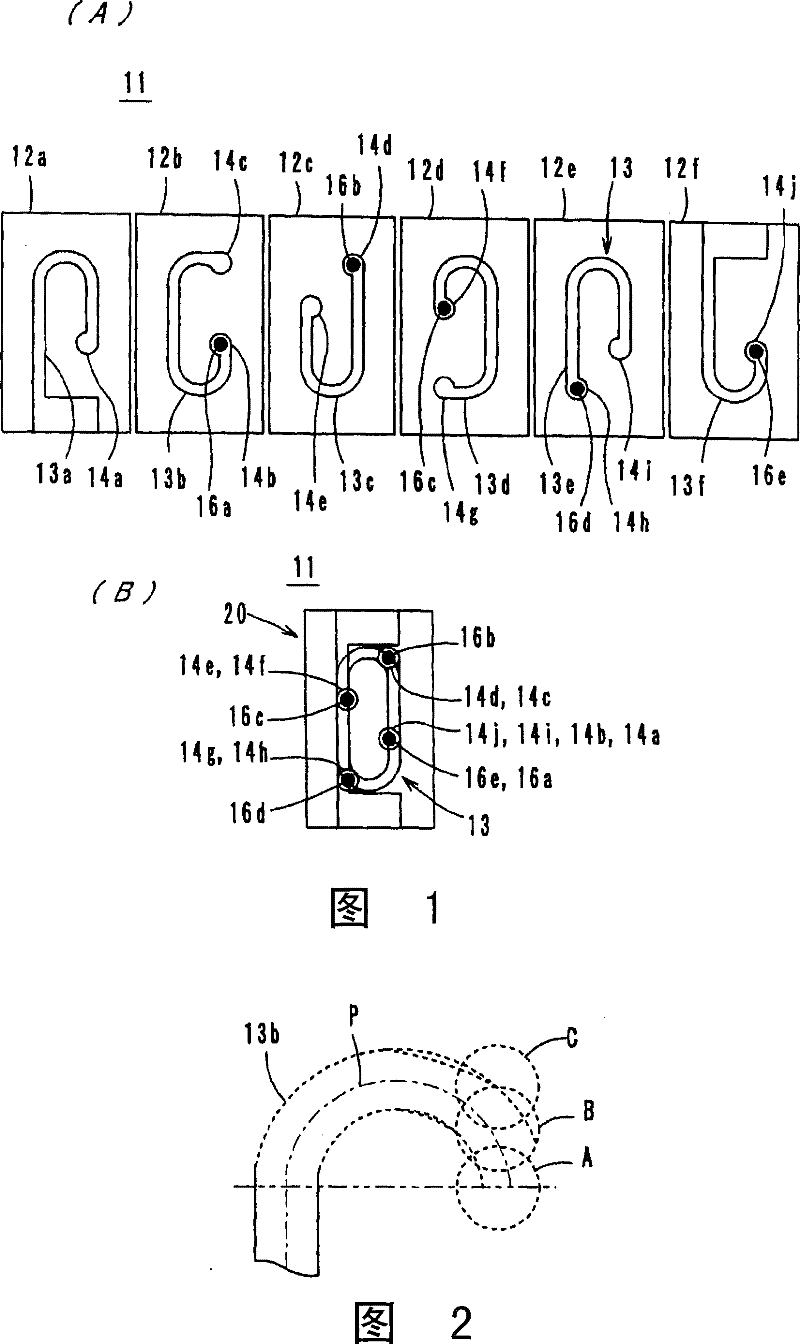
[0037] figure 1 (A) is an exploded plan view of the laminated coil component 11, figure 1 (B) is a perspective view inside the plan view of the laminated coil component 11 . Such as figure 1 As shown, in the laminated coil component 11, the ceramic green sheets 12a to 12f provided with the coil conductors 13a to 13f and the via hole conductors 16a to 16e are stacked in order from the sheet 12a to the sheet 12f, and then placed on top of each other. Laminated protective ceramic green sheets (not shown) are formed.

[0038] The ceramic green sheets 12a to 12f are produced as follows. First, various powders such as iron oxide, nickel oxide, copper oxide, and zinc oxide are weighed to form a predetermined ratio, and they are wet-mixed with a ball mill, and the dried material is pre-fired in a tunnel oven. The calcined powder is preliminarily crushed to be used as a ceramic raw material.

[0039] Next...

no. 2 Embodiment

[0059] (for the second embodiment, refer to image 3 )

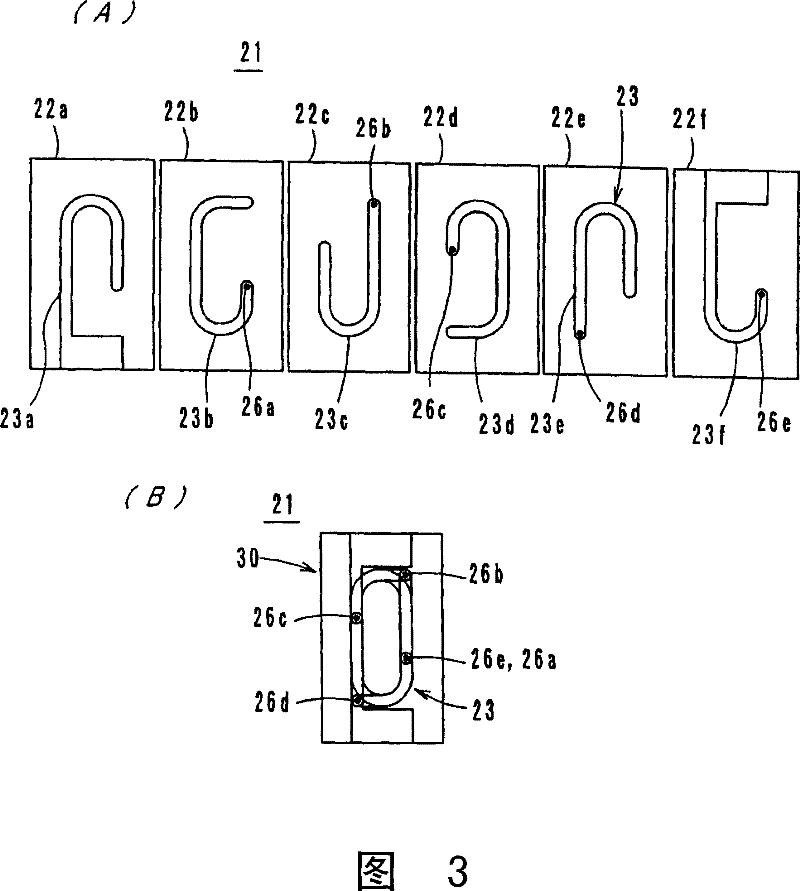
[0060] As a second example, a laminated coil component in which no pad is provided will be described. image 3 (A) is an exploded plan view of the laminated coil component 21, image 3 (B) is a perspective view inside the plan view of the laminated coil component 21 . Such as image 3 As shown, in the laminated coil component 21, the ceramic green sheets 22a-22f provided with the coil conductors 23a-23f and the via-hole conductors 26a-26e are stacked in order from the sheet 22a to the sheet 22f, and then placed on top of each other. Laminated protective ceramic green sheets (not shown) are formed.

[0061] This laminated coil component 21 incorporates a helical coil 23 in which coil conductors 23a to 23f are electrically connected in series via via conductors 26a to 26e provided at the ends of the coil conductors 23a to 23f. In addition, at least the inner periphery of the helical coil 23 is formed into a curved sha...

no. 3 Embodiment

[0067] (the 3rd embodiment, refer to Figure 4 )

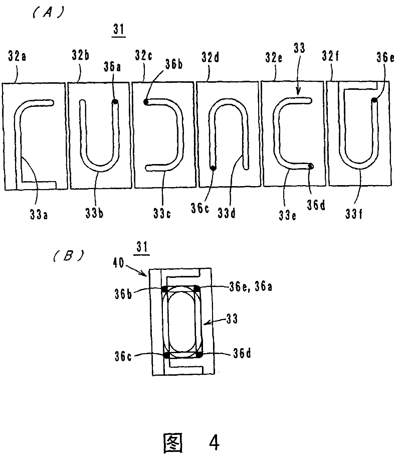
[0068] Figure 4 (A) is an exploded plan view of the laminated coil component 31, Figure 4 (B) is a perspective view inside the plan view of the laminated coil component 31 . Such as Figure 4 As shown in the laminated coil component 31, the ceramic green sheets 32a to 32f provided with the coil conductors 33a to 33f and the via hole conductors 36a to 36e are stacked in order from the sheet 32a to the sheet 32f, and then placed on top of each other. Laminated protective ceramic green sheets (not shown) are formed.

[0069] This laminated coil component 31 incorporates a helical coil 33 in which coil conductors 33a to 33f are electrically connected in series via via conductors 36a to 36e provided at ends of the coil conductors 33a to 33f.

[0070] The structure and manufacturing method of the third embodiment are basically the same as those of the aforementioned first and second embodiments. Therefore, the effect of the ...


PUM

PropertyMeasurementUnit
diameteraaaaaaaaaa

Abstract

The present invention results in a laminated coil component with less drop in inductance. Ceramic green sheets (22a) to (22f) formed with coil conductors (23a) to (23f) and through-hole conductors (26a) to (26e) are laminated, and the coil conductors (23a) to (23f) are passed through A laminated coil component of a helical coil (23) in which via-hole conductors (26a) to (26e) are connected in series. The via-hole conductors (26b), (26d) are positioned outside the helical coil (23), that is, on the end surface side of the laminate (30) in the longitudinal direction in a plan view in the stacking direction.

Description

technical field [0001] The present invention relates to a laminated coil component, and more particularly to a laminated coil component in which a helical coil is embedded in a laminated body composed of a plurality of ceramic layers. Background technique [0002] Conventionally, the laminated coil component described in patent document 1 is known as a laminated coil component, for example. like Figure 7 As shown in (A), in this laminated coil component 71, ceramic sheets 72a to 72f provided with coil conductors 73a to 73f and via-hole conductors 76a to 76e are stacked in order from sheet 72a to sheet 72f. Furthermore, protective ceramic sheets (not shown) are stacked up and down. The coil conductors 73 a to 73 f are connected in series via the via-hole conductors 76 a to 76 e to form the helical coil 73 . In addition, reference numerals 74a to 74j denote pads provided at the ends of the coil conductors 73a to 73f. Figure 7 (B) is a perspective view inside the plan view ...

Claims


Application Information

Patent Timeline
Patent Type & Authority Patents(China)
IPC IPC(8): H01F17/00
CPCH01F17/0013H01F2017/002H01F17/00
Inventor 小田原充前田智之
Owner MURATA MFG CO LTD
Why Eureka
Try Eureka