
Direct downward back light module

A backlight module, direct type technology, applied in optics, nonlinear optics, instruments, etc., can solve the problem of low brightness of backlight module

Inactive Publication Date: 2007-06-27
INNOCOM TECH SHENZHEN +1
View PDF0 Cites 28 Cited by
  • Summary
  • Abstract
  • Description
  • Claims
  • Application Information

AI Technical Summary

Problems solved by technology

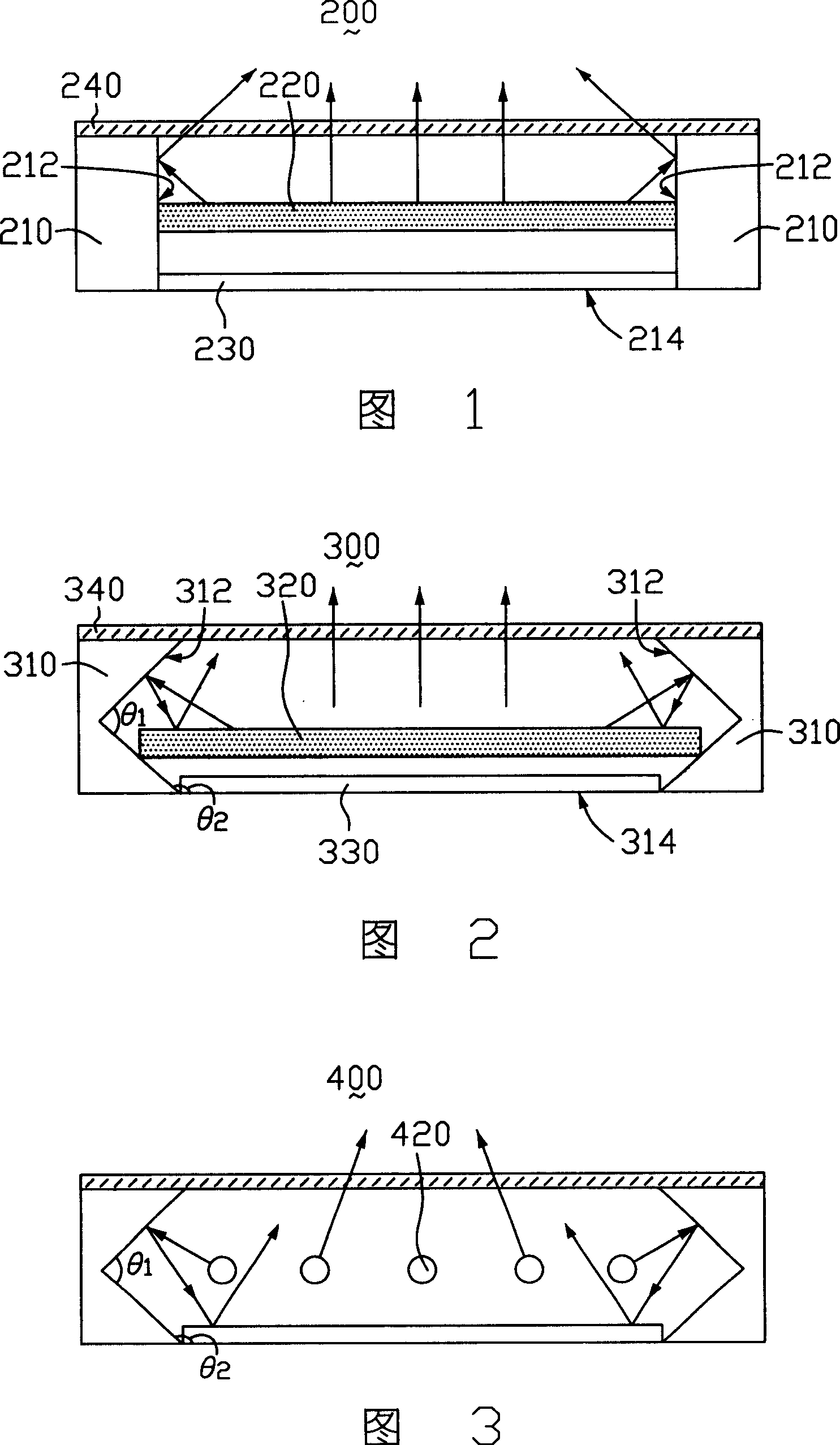
[0006] In order to solve the problem of low light output brightness of the prior art backlight module, it is necessary to provide a direct type backlight module with higher light output brightness

Method used


Image

  • Direct downward back light module
  • Direct downward back light module

Examples


Embodiment Construction

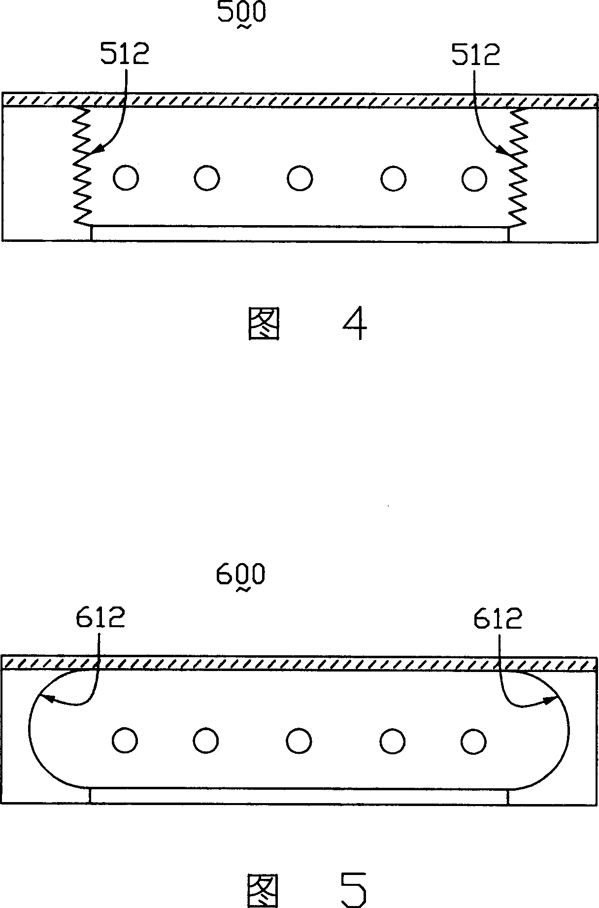
[0014] Please refer to FIG. 2 , which is a schematic structural diagram of the first embodiment of the direct type backlight module of the present invention. The direct type backlight module 300 includes a frame 310 , a light source 320 , a reflector 330 and a diffuser 340 . The frame 310 is generally a rectangular box structure with an opening, which is generally made of plastic, and includes four inner sides 312 and a bottom 314 , the four inner sides 312 are arranged opposite to each other and connected to the bottom 314 . The diffusion plate 340 is disposed on the opening of the frame 310 to form a closed space with the frame 310 for accommodating the light source 320 and the reflection plate 330 . The light source 320 is a linear light source, such as a cold cathode ray tube (cold cathode fluorescent lamp, CCFL), which abuts against two opposite inner sides 312 of the frame 310 and is parallel to the diffuser plate 240 . The reflection plate 330 is located on the bottom ...


PUM


Abstract

The full run-down type backlight module includes a frame, a light source, and a diffuser plate. The diffuser plate and the frame constitute an enclosed space in order to house the light source. The frame includes a bottom face, and multiple inner side faces connected to the bottom face. The inner side faces possess reflective condensation structure.

Description

【Technical field】 [0001] The invention relates to a backlight module, in particular to a direct type backlight module. 【Background technique】 [0002] The backlight module is a key component of the liquid crystal display, which can provide a light source with sufficient brightness to enable the liquid crystal panel to display normally. The backlight module can be roughly divided into two types according to the structure: side-light type and direct-light type. As the size of liquid crystal display devices increases and the brightness requirements increase, edge-lit backlight modules cannot provide sufficient brightness. Therefore, direct-lit backlight modules are widely used, which can increase the brightness by increasing the number of lamp tubes. [0003] FIG. 1 is a schematic structural diagram of a direct-lit backlight module in the prior art. The direct type backlight module 200 includes a frame 210, a linear light source 220, a reflector 230 and a diffuser 240. The fra...

Claims


Application Information

Patent Timeline
IPC IPC(8): G02F1/13357G02F1/133G02F1/1335
Inventor 张献文
Owner INNOCOM TECH SHENZHEN
Learn More