
Sliding door and window

A technology of sliding doors and windows and sliding fans, which is applied in the field of sliding doors and windows for buildings. It can solve the problems of easy dust accumulation in the U-shaped frame, affecting the drainage flow of drainage holes, and uneven inner and outer planes. Unobstructed automatic drainage, overall beautiful effect

Inactive Publication Date: 2007-07-11
许梅
View PDF0 Cites 4 Cited by
  • Summary
  • Abstract
  • Description
  • Claims
  • Application Information

AI Technical Summary

Problems solved by technology

[0004] However, the biggest disadvantage of the sliding doors and windows of these two structures in daily practical application is the drainage problem. Since the drainage of the above structure is realized by punching holes in the upper wall of the frame material and the bottom of the outer side wall to form a drainage channel, so In the weather of heavy rain and strong wind, because there is no obvious pressure difference on both sides of the U-shaped structure to affect the drainage flow of the drainage hole, a large amount of water will appear on the inner side of the frame, and in severe cases, the rainwater will overflow into the room , causing inconvenience to users; and the U-shaped frame is easy to accumulate dust and is not easy to clean
In addition, the fixed sliding doors and windows are composed of uneven inner and outer planes, which affects the overall appearance; as the main force-bearing parts, the frame and stiles use "U"-shaped lining steel, which affects the overall strength

Method used


Image

  • Sliding door and window
  • Sliding door and window

Examples


Embodiment Construction

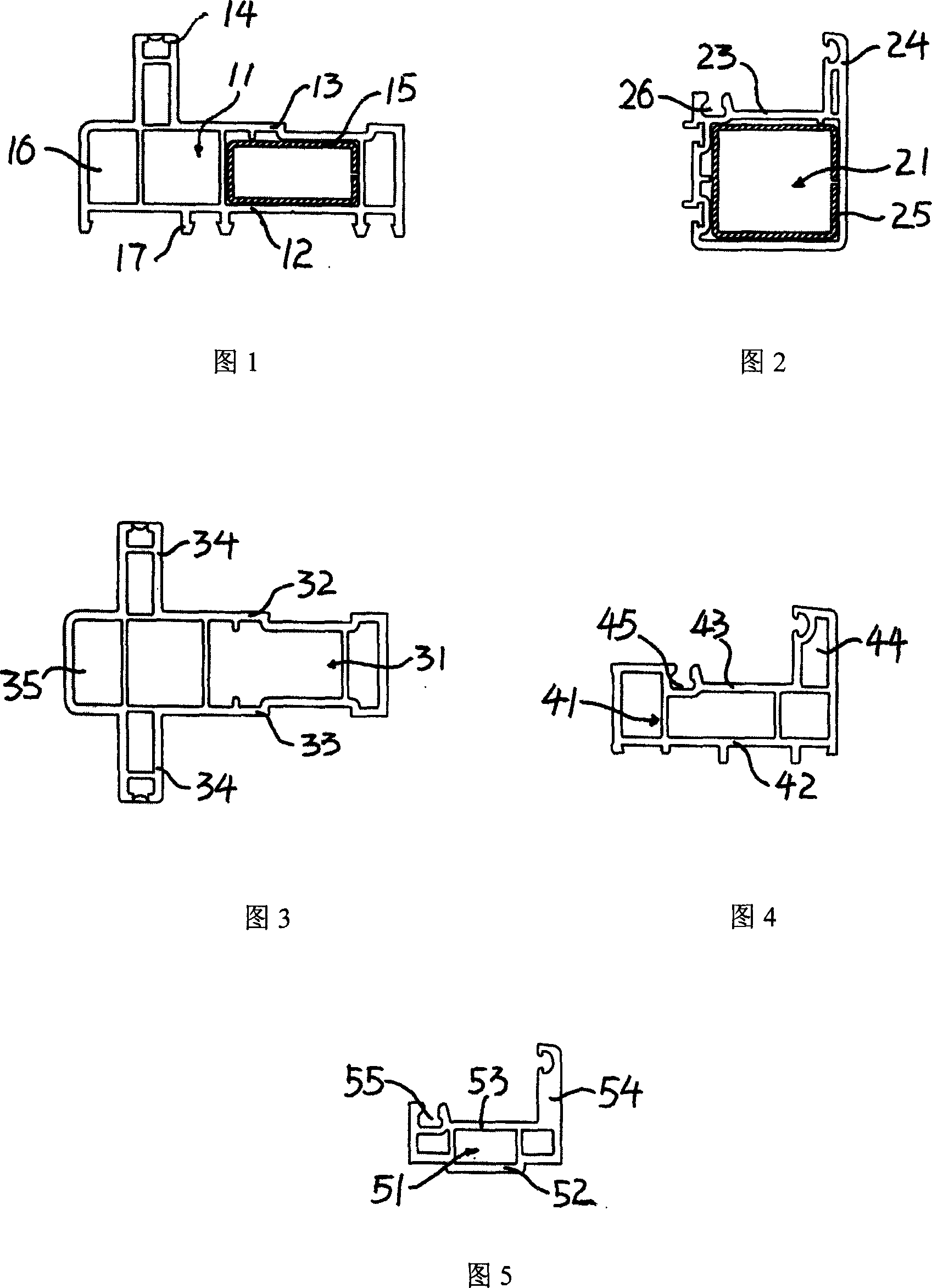
[0020] In Fig. 1, the frame material 1 is made up of a rectangular frame body 11 and a slide rail 14. There are protruding cards 17 on the bottom wall 12 of the rectangular frame body 11, and the bottom wall 12 is fixed in the wall. There is a protrusion 14 on the parallel upper wall 13 corresponding to the bottom wall 12, and the protrusion is a slide rail. The frame body 11 also extends a cavity 16 from one side of the support arm 14, and the cavity 15 is a rectangular lining steel.

[0021] In Fig. 2, a support arm 24 perpendicular to it is provided at the edge position of the upper wall 23 of the upper wall 23 of the fixed stile material 2 of the fixed sash material 2 of the fixed fan when assembled with the frame material 1, and the upper wall far away from the support arm 24 23 other side end places are provided with batten groove 26, and the section shape of stile 2 is " L " shape, and the cavity shape of stile frame 21 is square, and square liner steel 25 is arranged i...


PUM


Abstract

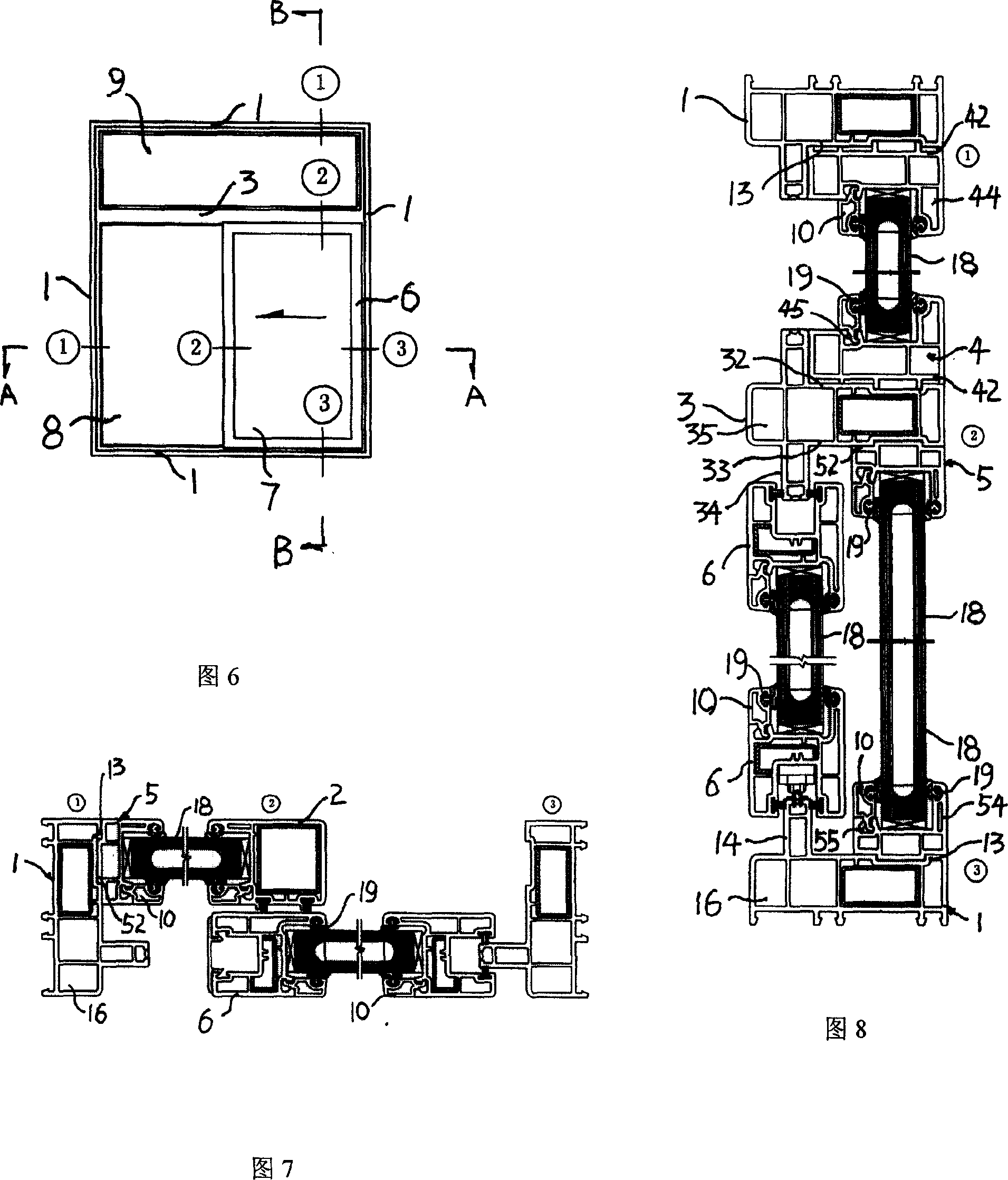
The invention discloses a sliding door and window. Fixed sliding door and window structure comprises fixed sector and sliding sector. The fixed sector comprises frame material and fixed sector material. The sliding sector comprises sliding sector material. A convex rail is set on the upper wall of rectangle frame of frame material and the sliding sector is set on the rail of frame material. Assistant frame with the section of L-shape is fixed on the upper wall of frame constituting fixed sector. A support arm vertical with the upper wall of bottom frame of assistant frame is set at one end of upper wall. The lower wall of bottom frame of assistant frame is combined with the upper of frame body and there is layering groove in the upper wall of bottom frame of assistant frame. Compared with prior technology, the invention is provided with better water drainage performance, saving material and assembling workload. They are improved that intensity, water-tightness, air-tightness, safety.

Description

Technical field: [0001] The technical solution to be protected by the present invention belongs to the technical field of building sliding doors and windows. Background technique: [0002] At present, the sliding doors and windows most commonly used by people are mainly composed of frames and fan profiles made of aluminum alloys, plastics and other materials, and sometimes stiles are used to form some sliding doors and windows with more complicated structures. For the profiles that make up the double sliding doors and windows, the cross-sectional shape of the frame material consists of a rectangular frame and two protrusions on the upper wall of the frame to form a "U"-shaped structure. The protrusions function as slide rails, and the fan material The composed sliding windows or sliding doors are installed on the slide rails through pulleys. For sliding doors and windows of this structure, no matter whether two or more sliding fans are used, the area of ​​the indoor and out...

Claims


Application Information

Patent Timeline
Patent Type & Authority Applications(China)
IPC IPC(8): E06B3/46E06B7/16
Inventor 许梅
Owner 许梅
Learn More