Data converting circuit and display apparatus using the same

A technology for converting circuits and data, applied in color signal processing circuits, static indicators, cathode ray tube indicators, etc., can solve problems such as large chip size

Inactive Publication Date: 2007-07-11
NEC ELECTRONICS CORP
View PDF1 Cites 3 Cited by
  • Summary
  • Abstract
  • Description
  • Claims
  • Application Information

AI Technical Summary

Problems solved by technology

Therefore, the LUT size is increased, thereby requiring a large chip size

Method used


Image

  • Data converting circuit and display apparatus using the same
  • Data converting circuit and display apparatus using the same
  • Data converting circuit and display apparatus using the same

Examples


no. 1 example

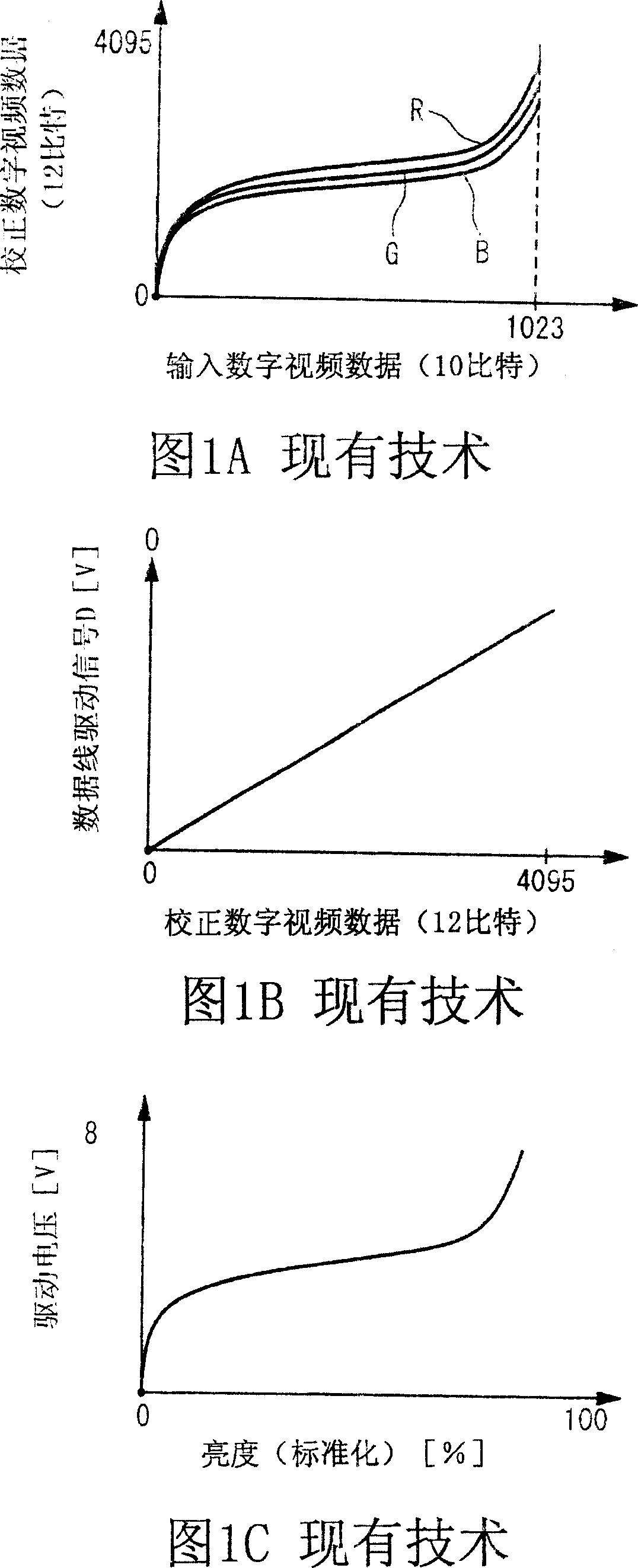
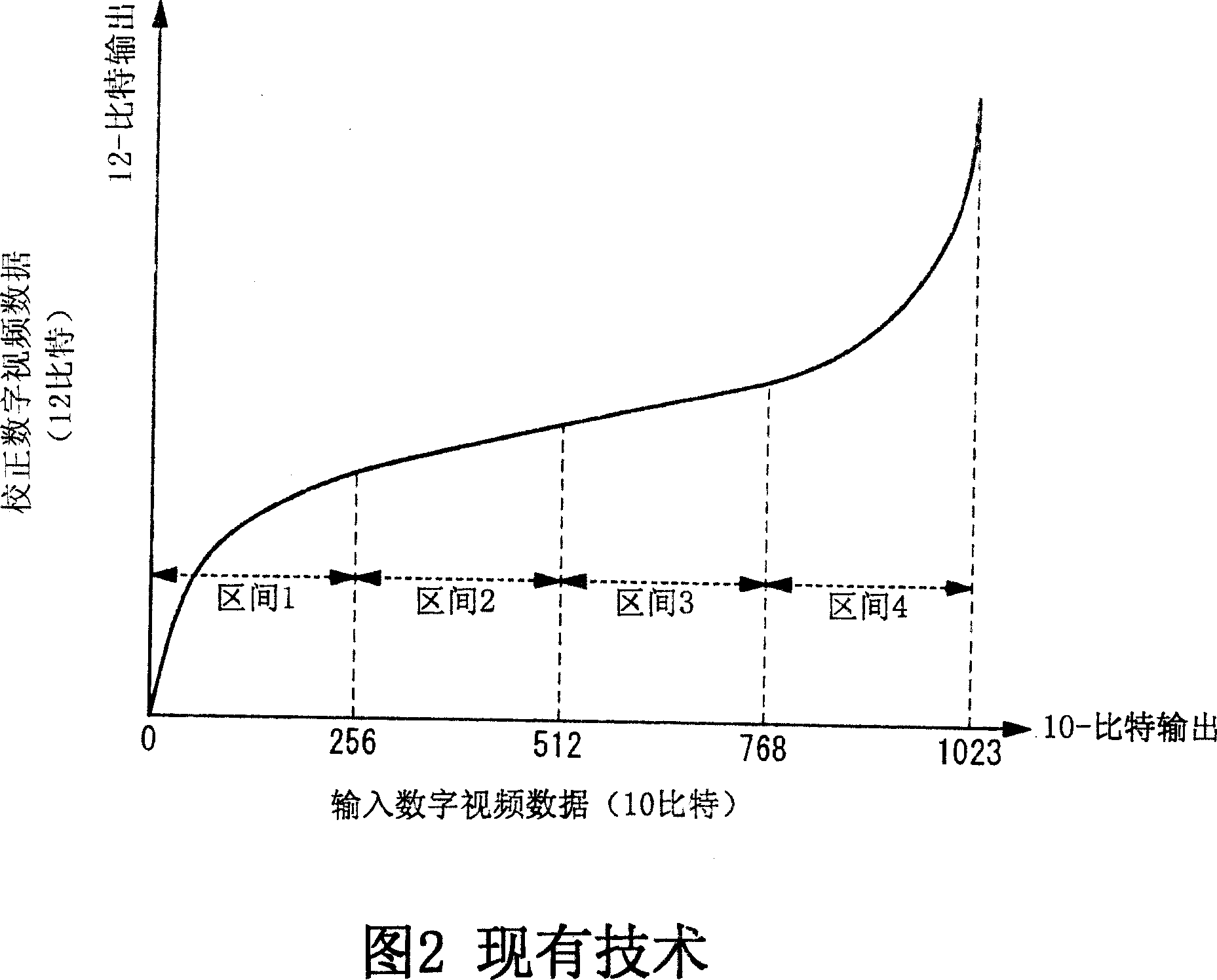
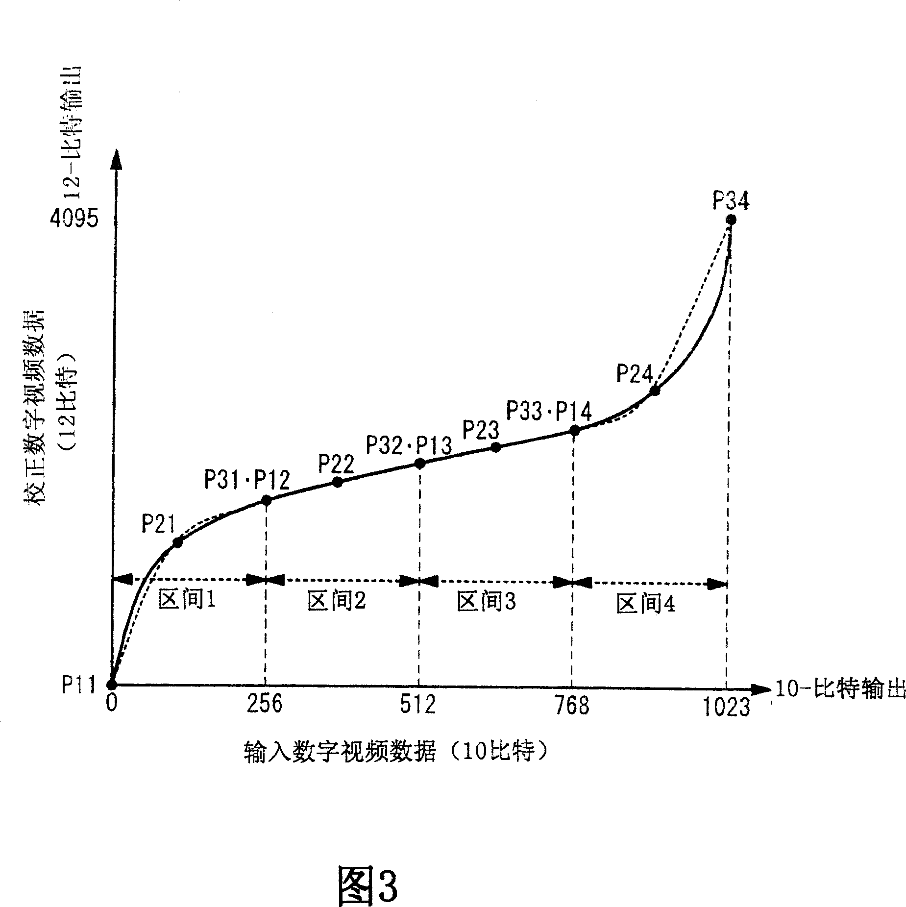
[0058] In the data conversion circuit according to the first embodiment of the present invention, as shown in FIG. 3 , approximation calculation of 4 divisions is performed by using a quadratic curve. The pixel data of the input digital video data has 10 bits, and the pixel data of the corrected digital video data after conversion has 12 bits. In general, when performing approximate calculations using an nth-order equation (n is an integer of 1 or more), it is necessary to set (n+1) control points on the curve. Therefore, in the case of a quadratic curve, 3 control points need to be set on the curve for each interval. These 3 control points are usually the start point P1, the curve passing point P2 at the center of the calculation interval, and the end point P3. As shown in FIGS. 4A and 4B , since the control points P1 , P2 , P3 are set to true values ​​(with 12 bits each), the original curve can be approximately represented. However, due to the approximate calculation, ther...

no. 2 example

[0076] A data conversion circuit according to a second embodiment of the present invention will be described below. In the second embodiment of the present invention, as shown in FIG. 12, similarly to the first embodiment, the section is divided into 4 sections. However, the second embodiment differs from the first embodiment in that a linear equation (approximately a straight line) is used. In the case of a straight line approximation, for each interval, two control points on the curve are required. As shown in FIGS. 13A and 13B , start point 1 and end point 2 are used as the two control points. Since the control points P1 and P2 are set to true values ​​(with 12 bits each), the original curve becomes approximately a straight line. In the case of a straight line approximation, the relationship between the error and the input digital video data is always as shown in FIG. 14 . This example is characterized in that the calculation error is 0 at the points P1 and P2, and the c...


PUM


Abstract

In a data converting circuit, an approximation calculation circuit calculates an approximation value of an output to input data by using an n-th order equation (n is an integer equal to or more than one). An error reducing circuit generates an error correction value by using a multiplication factor determined based on the input data. An addition section adds the approximation value and the error correction value and outputs an addition result.

Description

technical field [0001] The present invention relates to a data conversion circuit for converting input video data, and a display device using the data conversion circuit. Background technique [0002] In general television broadcasting, the video signal of the broadcasted video image is subjected to gamma correction to match the IT (current-brightness) characteristic of a cathode ray tube, and then a compensating resultant signal is transmitted. Therefore, when displaying a video signal on a display device other than a cathode ray tube (CRT), it is necessary to perform gradation correction (hereinafter referred to as gamma correction) matching the driving voltage-luminance characteristic of the display device. By applying gamma correction, the contrast of the original image can be accurately reproduced while matching the brightness levels of the original image. Also, even in the case of a color image, by individually applying gamma correction to each of the three primary co...

Claims


Application Information

Patent Timeline
Patent Type & Authority Applications(China)
IPC IPC(8): H04N9/69G09G5/00G09G5/06G09G5/10G09G3/36
CPCG09G3/2007G09G2340/0428G09G2320/0271
Inventor 梅田谦吾堀良彦
Owner NEC ELECTRONICS CORP
Why Eureka
Try Eureka