Rotary flame heater

a heater and rotary technology, applied in the field of heaters, can solve the problems of reducing the contact area of the heater, reducing the contact area, and reducing the rotation speed of the rotary flame, so as to facilitate assembly, increase the contact area, and save spa

Active Publication Date: 2018-06-19
WANG PENGYU
View PDF11 Cites 0 Cited by
  • Summary
  • Abstract
  • Description
  • Claims
  • Application Information

AI Technical Summary

Benefits of technology

[0008]Preferably, a height of the ignition device is the same with a height of the plurality of first air inlet passages, an inner diameter of the first wind wheel is less than the size of the burner, a bottom of the first wind wheel is fit with a top surface of the burner. The first wind wheel is configured to mix more air before the mixed gas contacts the air coming from the plurality of second air inlet passages, and provides a rotary path for air when air enters into the first wind wheel at the same time, and thereby provides an initial rotation power. Furthermore, rotary flame has stronger rotate speed than ordinary flame, which may extinguish a long burning fire generated by the ignition device and as a result extinguish the whole burner. As the first air inlet passage is set aslant, the inner wall of the first air inlet passage can be used to block the long burning fire, which avoids extinguishing the long burning fire.
[0010]Furthermore, a size of the air inlet hole is 8 mm*20 mm. The size of existing air inlet hole is 16 mm*12 mm, in order to ensure large amount of air to support the fuel gas and to avoid carbon deposition. In the present invention, a second air inflow is needed through the second air inlet passage to provide enough rotating power, so the size of air inlet hole is decreased. The mixed gas in the burner still needs more air to mix for sufficient burning. The second air inflow in the second air inlet passage can not only make the gas burnt adequately to avoid carbon deposition, but also improve rotating power of the flame.
[0013]Preferably, the plurality of first blades and the plurality of second blades are both arc-shaped to ensure a good rotating effect of the first air inflow and the second air inflow.
[0016]Preferably, for facilitating the assembling of the glass tube, a top surface of the upper mounting plate is set with an annular limiting plate projecting from the top surface, an outer diameter of the annular limiting plate matches with an inner diameter of the glass tube, an external of the glass tube is set with a protection net. The glass tube is sleeved on an external of the annular limiting plate to fix the glass tube effectively. The protection net set on the external of the glass tube can avoid scald by contacting the glass tube.
[0017]Preferably, for facilitating the assembling of the burner, the first wind wheel and the second wind wheel, the rotary flame heater further comprises a mounting cap, the mounting cap is set with a through-hole in the center, the burner and the first wind wheel are mounted within the mounting cap, the second wind wheel is mounted on an upper end of the mounting cap, the first wind wheel, the second wind wheel and the through-hole are set co-axially, the mounting cap is set with a plurality of vents connected with external, a bottom of the mounting cap is set with a mounting cavity for mourning a fuel gas source. The fuel gas source, such as a gas cylinder, is placed within the mounting cavity, which saves much space.
[0018]Beneficial effects: this application adds a first wind wheel and a second wind wheel in the upper end of the burner, and retains the glass tube, which can make the flame to generate a rotating effect. The rotary flame can make full use of the combustion space, increase the contacting area with the glass tube and increase the calorific value when burns the same gas, which achieves a better heating effect.

Problems solved by technology

Furthermore, rotary flame has stronger rotate speed than ordinary flame, which may extinguish a long burning fire generated by the ignition device and as a result extinguish the whole burner.

Method used


Image

  • Rotary flame heater
  • Rotary flame heater
  • Rotary flame heater

Examples


embodiment

[0031

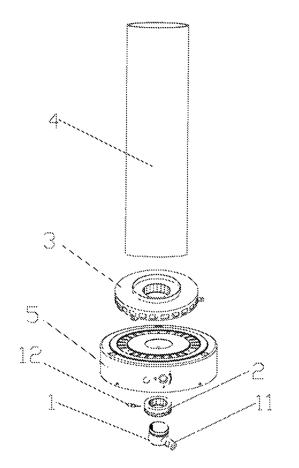
[0032]As shown in FIGS. 1, 5, 6, and 8-10, a rotary flame heater, comprises mounting cap 5 as well as burner 1, first wind wheel 2, second wind wheel 3 and glass tube 4 which are set in sequence from bottom to top. Mounting cap 5 is set with through-hole 51 in the center. Burner 1 and first wind wheel 2 are mounted within mounting cap 5, second wind wheel 3 is mounted on an upper end of mounting cap 5. First wind wheel 2, second wind wheel 3 and through-hole 51 are set co-axially. Mounting cap 5 is set with vent 52 which is connected with external. A bottom of mounting cap 5 is set with a mounting cavity 7 for mounting a fuel gas source.

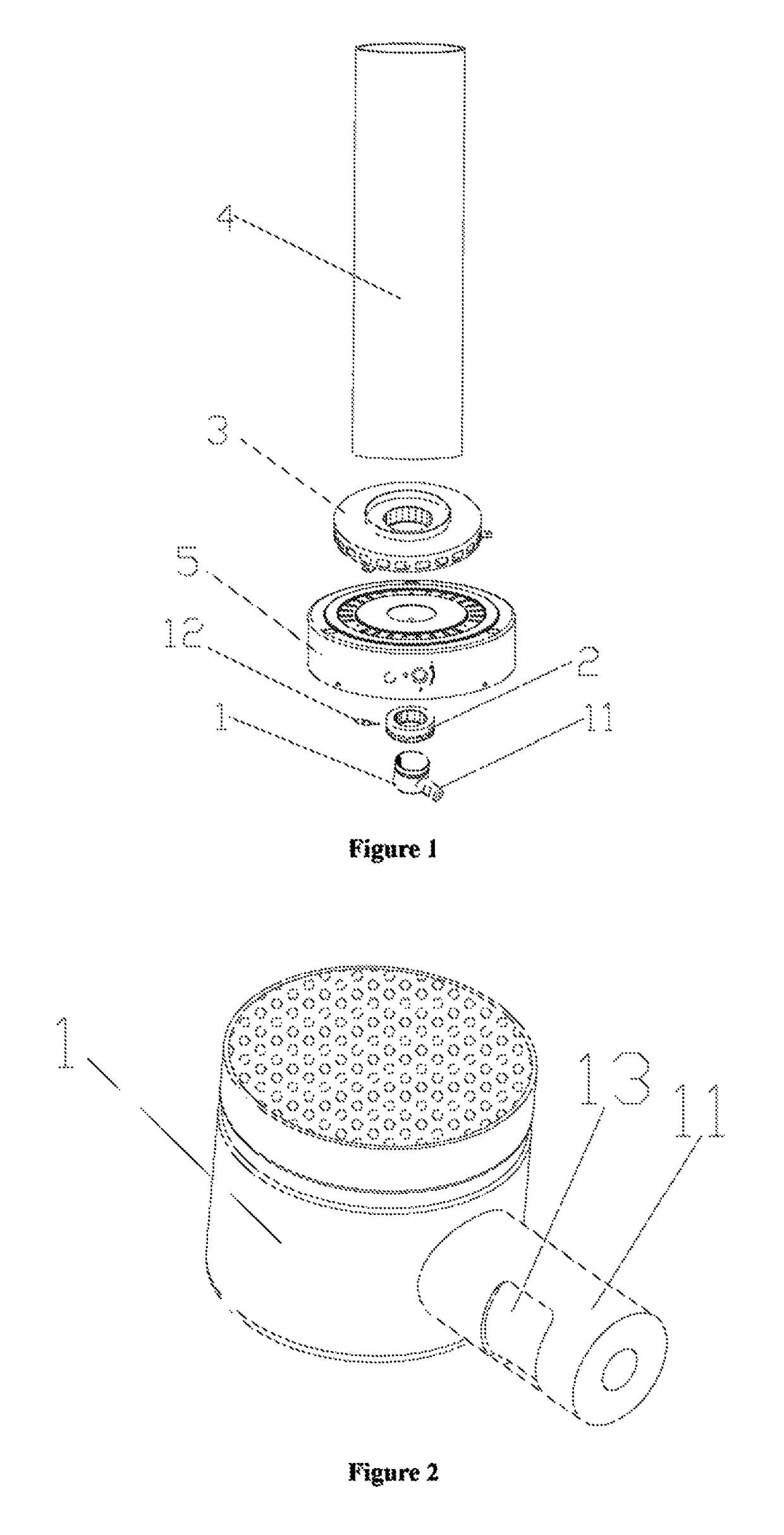
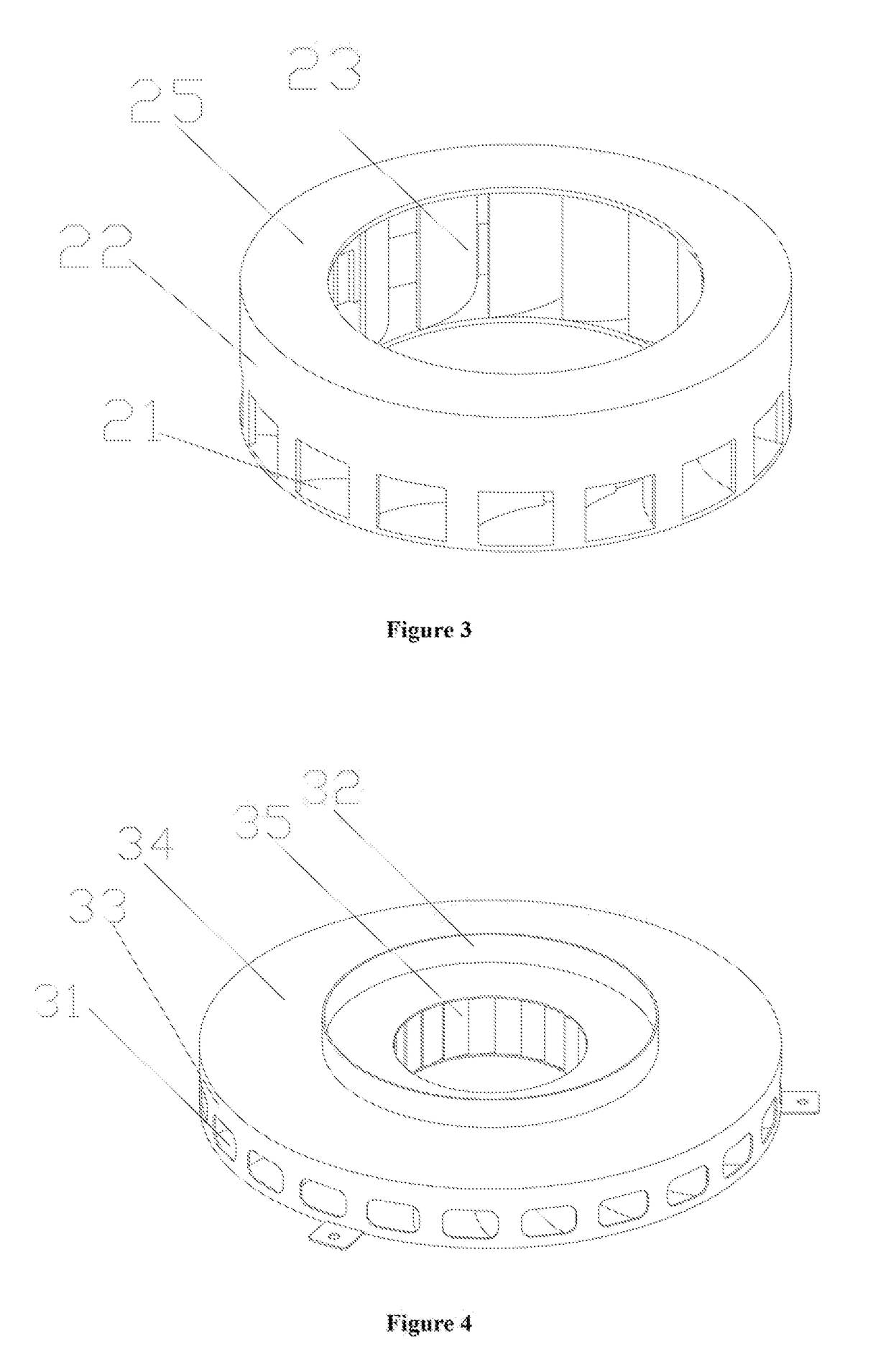
[0033]As shown in FIGS. 1, 3, 4, 6 and 9, one side of burner 1 is set with ignition device 12. First wind wheel 2 and second wind wheel 3 are both annular. A side wall of first wind wheel 2 is aslant set with a plurality of first air inlet passages 21. A height of ignition device 12 is the same with a height of the plurality of first air inlet p...


PUM


Abstract

This invention relates to a rotary flame heater, comprising a burner, a first wind wheel, a second wind wheel and a glass tube set in sequence from bottom to top; one side of the burner is set with an ignition device, the first wind wheel and second wind wheel are annular, a plurality of first air inlet passages are aslant set on a side wall of the first wind wheel, a plurality of second air inlet passages are aslant set a side wall of the second wind wheel, the inclined direction of the plurality of first air inlet passages is the same with that of the second air inlet passages. The advantage of this invention is to make full use of the combustion space, increase the contacting area with the glass tube and increase the calorific value when burns the same gas, which achieves a better heating effect.

Description

TECHNICAL FIELD OF THE INVENTION[0001]This invention relates to field of heater, in particular relates to a rotary flame heater.BACKGROUND[0002]About existing glass tube heater on the market, no matter what diameter of the glass tube it is, the flame all burns vertically with a same ornamental effect, as a result the flame does not make a full use of the combustion space in the internal of the glass tube. The flame as a whole is vertically upward and does not contact with the glass tube directly.[0003]Under such circumstances, because the diameter of the flame only occupies part of the diameter of the glass tube, the flame is unable to hit the inner wall of the glass tube directly. As a result, the inner wall of the glass tube cannot be heated adequately, and the glass tube is unable to dissipate heat well, which fails to achieve the purpose of heating. Furthermore, the shape of the flame of the heater is dull and rigid.[0004]Existing solutions such as patent App. No. 201410377119.0...

Claims


Application Information

Patent Timeline
Patent Type & Authority Patents(United States)
IPC IPC(8): F23D14/12F24D19/06F23D14/70F23D14/84
CPCF23D14/70F23D14/12F23D14/84F24D19/06F23D14/151
Inventor WANG, PENGYU
Owner WANG PENGYU
Why Eureka
Try Eureka