

Electrolysis stack and electrolyzer
a technology applied in the field of electrolyzer and stack, can solve the problems of high cost of dc-dc regulator and easy error, and achieve the effect of prolonging the service life of the electrolyzer
- Summary
- Abstract
- Description
- Claims
- Application Information
AI Technical Summary
Benefits of technology
Problems solved by technology
Method used
Image

Examples
Embodiment Construction
[0075]“(Switchable) segmented electrolysis stack of an electrolyzer” (FIG. 2)
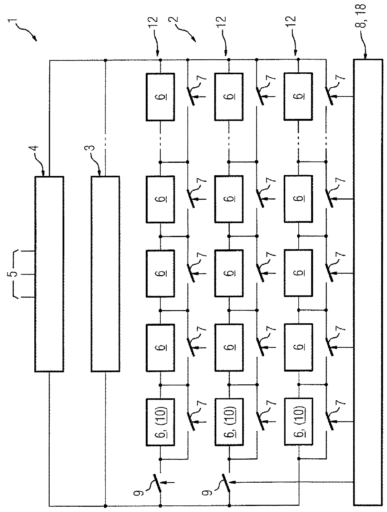
[0076]FIG. 2 shows one of a plurality of controllable electrolysis stacks 6, these having an identical structure in each case and being interconnected in parallel, of a (here) PEM electrolyzer 2 for hydrogen electrolysis (subsequently referred to simply as electrolyzer 2).
[0077]The electrolyzer 2 is directly attached (not shown) to a regenerative energy source 3, here a photovoltaic installation or a photovoltaic field (abbreviated as PV installation or PV field respectively) 3, by means of which it is supplied with DC voltage that produces the hydrogen electrolysis in the electrolyzer 2.
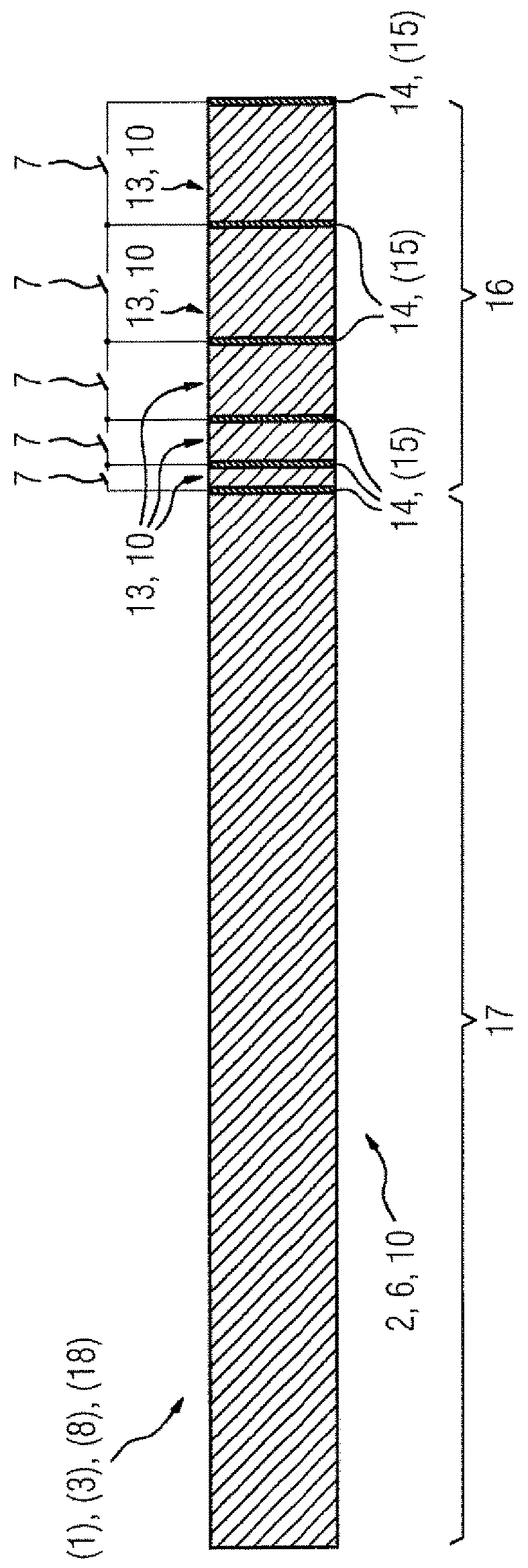
[0078]The electrolysis stacks 6 are each, or the single electrolysis stack 6 shown in FIG. 2 is, constructed from a multiplicity of electrolysis cells 10, here a total of 250 electrolysis cells 10, which are electrically connected in series.
[0079]The total number of all electrolysis cells 10 of the electrolyzer 2 coordinate...
PUM
 Abstract
Description
Claims
Application Information