Heat dissipation structure with splitted chimney structure

a technology of heat dissipation structure and chimney structure, which is applied in the direction of point-like light sources, lighting and heating apparatus, lighting device details, etc., can solve the problems of negative impact on the lifetime of drivers, and achieve the effect of improving the heat dissipation structure and enhancing the convection cooling of lighting devices

Active Publication Date: 2018-06-26
KONINK PHILIPS ELECTRONICS NV
View PDF26 Cites 4 Cited by
  • Summary
  • Abstract
  • Description
  • Claims
  • Application Information

AI Technical Summary

Benefits of technology

[0004]It is an object of at least some embodiments of the present invention to provide an improved heat dissipation structure for a lighting device (or lamp). In particular, it is an object to provide a heat dissipation structure for enhancing convection cooling of the lighting device.

Problems solved by technology

In conventional LED-based lighting devices, the light source and the driver have a common heat sink, whereby heat generated by the LEDs is transferred to the driver via the heat sink, which may have a negative impact on the lifetime of the driver since the driver is sensitive to high temperatures.

Method used


Image

  • Heat dissipation structure with splitted chimney structure
  • Heat dissipation structure with splitted chimney structure
  • Heat dissipation structure with splitted chimney structure

Examples


Embodiment Construction

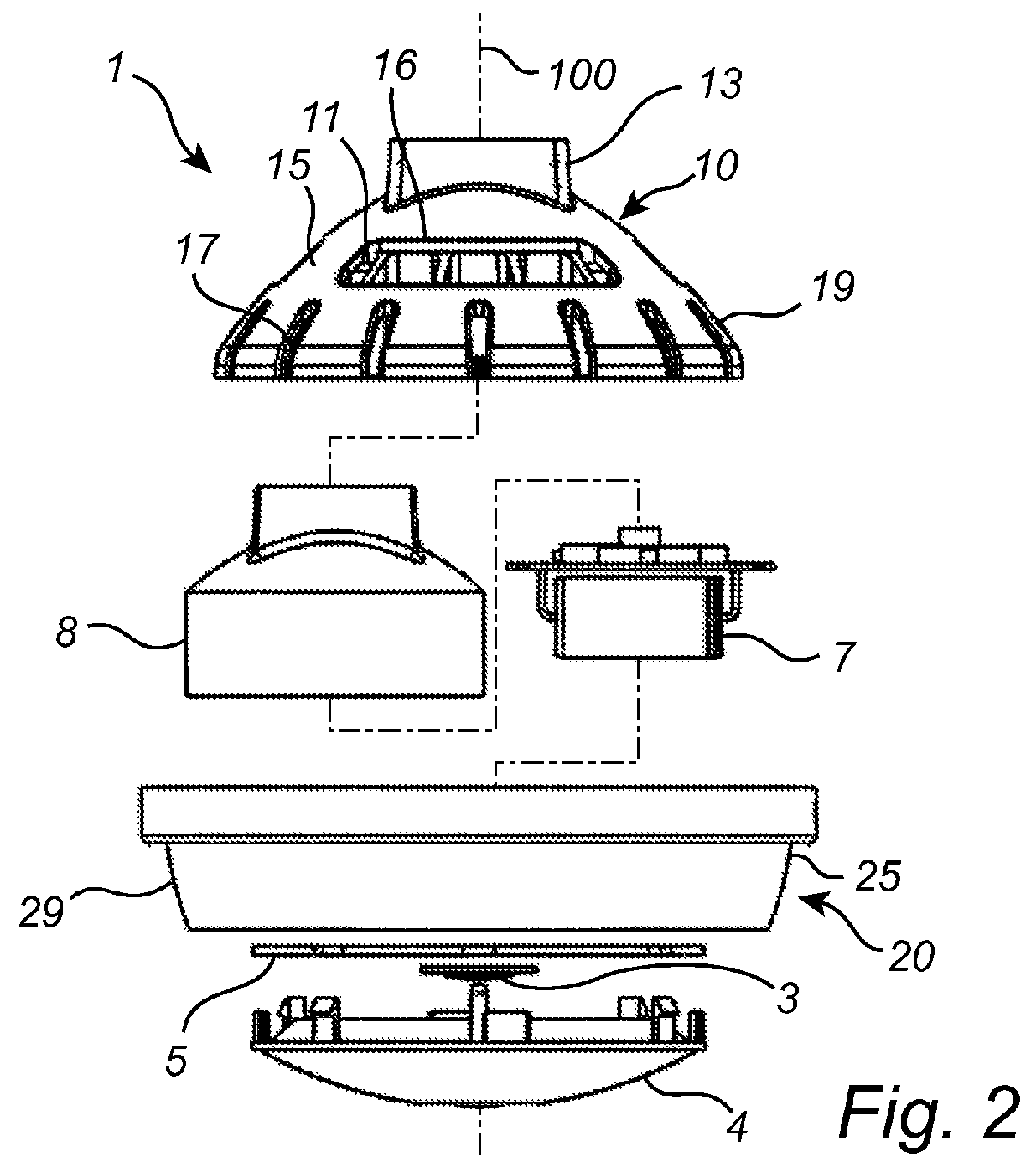
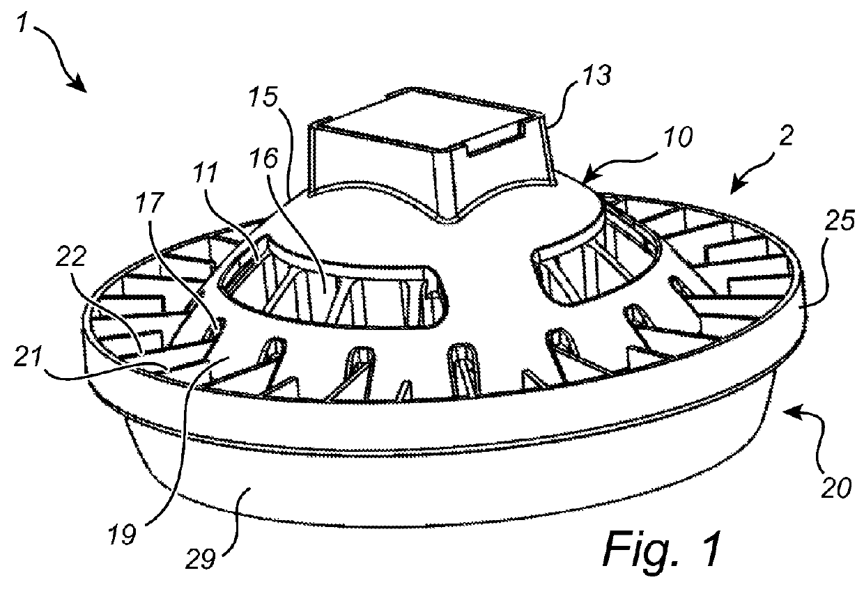
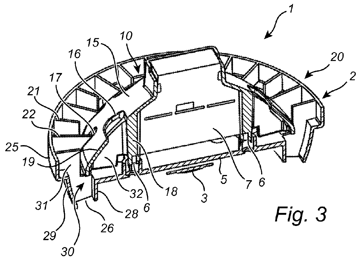
[0034]With reference to FIGS. 1 to 4, a lighting device 1 comprising a heat dissipation structure 2 according to an embodiment of the present invention will be described.

[0035]The lighting device 1 comprises at least one light source 3 and electronics 7 for driving the light source 3 (in the following referred to as the driver 7), as shown in FIG. 2. The driver 7 may be encapsulated in potting (or pottant) for protection against moisture and shocks, and supported in a housing (or holder) 8. The light source 3 may be a solid state based light source, such as a light emitting diode (LED). Optionally, a lens 4 or an optical cover may be arranged to enclose the light source 3 in the lighting device 1.

[0036]The heat dissipation structure 2 of the lighting device 1 is configured to dissipate heat from the lighting device 1. The heat dissipating structure 2 comprises a heat sink 10 for dissipating heat from the driver 7 (in the following referred to as the driver heat sink) and a heat sink...


PUM


Abstract

A heat dissipation structure (2) for a lighting device (1), comprising: at least two separate heat sinks (20, 10) for a light source (3) and a driver (7) for the light source (1), respectively, each heat sink (20, 10) comprising fins (21, 22, 11) and a wall arrangement (15, 25), wherein said at least two separate heat sinks (20, 10) are disposed along an axial direction of the lighting device (1), wherein the fins (21, 22, 11) of said at least two separate heat sinks (20, 10) are enclosed by the wall arrangements (15, 25) to form a chimney structure (30) arranged along said axial direction of the lighting device (1), and wherein the chimney structure (30) comprises at least two sub-chimney structures (31, 32) arranged fluidly in parallel to provide two air flows simultaneously, which reduces heat concatenation.

Description

CROSS-REFERENCE TO PRIOR APPLICATIONS[0001]This application is the U.S. National Phase application under 35 U.S.C. § 371 of International Application No. PCT / IB13 / 056657, filed on Aug. 15, 2013, which claims the benefit of International Application No. PCT / CN2012 / 085546 filed Nov. 29, 2012 and International Application No. PCT / CN2012 / 080302 filed Aug. 17, 2012. These applications are hereby incorporated by reference herein.FIELD OF THE INVENTION[0002]The present invention generally relates to the field of heat dissipation structures for lighting devices. In particular, the present invention relates to such heat dissipation structures comprising chimney structures for dissipating heat from lighting devices by means of convection.BACKGROUND OF THE INVENTION[0003]Traditional incandescent lamps are currently being replaced by more energy efficient solid state based alternatives, such as light emitting diode (LED) based lighting devices. LEDs, as well as electronics for driving the LEDs,...

Claims


Application Information

Patent Timeline
Patent Type & Authority Patents(United States)
IPC IPC(8): F21V29/00F21V29/83F21V29/508F21V29/77F21V23/02F21V29/503
CPCF21V29/777F21V29/83F21V29/508F21Y2101/00F21V29/503F21V29/713F21V29/773F21K9/233F21Y2115/10F21V29/70
Inventor XUE, JIANLEI, CHENGYONG
Owner KONINK PHILIPS ELECTRONICS NV
Why Eureka
Try Eureka