Check patentability & draft patents in minutes with Patsnap Eureka AI!

Stitch-size controllable knitting machine, and manufacturing method of knitted fabric

a knitting machine and stitching technology, applied in knitting, weft knitting, textiles and papermaking, etc., can solve the problems of difficult increase in difficulty in increasing the number of the selector butts in the vertical direction, and failure to select the sinker. , to achieve the effect of increasing the rotation speed of the cylinder and preventing the failure of the selection of the sinker

Inactive Publication Date: 2018-07-03
OKAMOTO INDS
View PDF17 Cites 1 Cited by
  • Summary
  • Abstract
  • Description
  • Claims
  • Application Information

AI Technical Summary

Benefits of technology

[0008]Preferred embodiments of the present invention provide a stitch size controllable knitting machine which can control the stitch size on a stitch-by-stitch basis and can increase a rotation speed of a cylinder thereof while preventing a failure of selection of a sinker.
[0009]Preferred embodiments of the present invention also provide a manufacturing method of knitted fabric by using a knitting machine which can control the stitch size on a stitch-by-stitch basis, which enables a rotation speed of a cylinder of the knitting machine to be increased while preventing a failure of selection of a sinker.
[0014]In the aforementioned arrangement of the stitch-size controllable knitting machine, the sinkers and the selector jacks are separate components from each other and the selector jacks radially outside the sinkers are provided with the selector butts. Therefore, the selector butts of different steps can be arranged in the radial direction. Moreover, the selector butts of circumferentially adjacent selector jacks can be arranged at one or more different radial directions. Thus, this arrangement can correspond to high-speed rotation of the cylinder. Therefore, even in a case of high-speed rotation of the cylinder, selection of the selector butts can be surely and reliably performed.
[0015]In addition, in the aforementioned arrangement of the stitch-size controllable knitting machine, a mechanism is provided in which the selector jack pushes its corresponding sinker out by the action of the cam. Thus, the movement of the sinker is synchronized with the action of the cam. Therefore, the position of the sinker is limited by the cam, so that stable positioning of the sinker can be realized. Consequently, the occurrence of problems can be reduced and productivity can be improved. For example, the stitch sizes of larger and small stitches can be stably obtained.
[0016]Furthermore, when the sinkers and the selector jacks are separate components from each other and the selector jacks are arranged radially outside the sinkers, it is possible to easily keep the space for the actuator which is to act on the selector butts, radially outside the cylinder. That is, the actuator can be arranged at a more radially outward position.

Problems solved by technology

However, increasing the rotation speed of the cylinder can cause failure or omission of selection of the selector butt.
This makes it difficult to increase the number of the selector butts in the vertical direction and therefore an increase in the rotation speed of the cylinder is difficult.

Method used


Image

  • Stitch-size controllable knitting machine, and manufacturing method of knitted fabric
  • Stitch-size controllable knitting machine, and manufacturing method of knitted fabric
  • Stitch-size controllable knitting machine, and manufacturing method of knitted fabric

Examples


first preferred embodiment

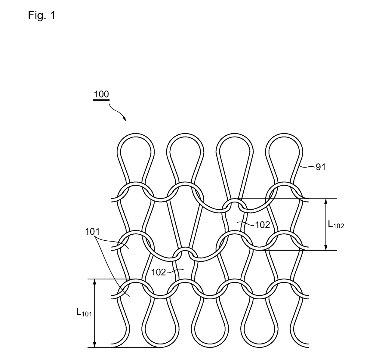
[0078]Knitted fabric which can be formed by a circular knitting machine (stitch size controllable knitting machine) according to the first preferred embodiment is now described. FIG. 1 shows exemplary knitting structures (knitted fabric) which can be formed by the circular knitting machine of the first preferred embodiment. Referring to FIG. 1, the knitted fabric 100 includes stitches of a plurality of stitch sizes. For example, the knitted fabric 100 includes a first stitch 101 and a second stitch 102 having a smaller stitch size than the first stitch 101, as shown in FIG. 1. For example, the difference L101−L102 of the stitch size between the first stitch 101 and the second stitch 102 preferably is about 0.1 mm to about 2.0 mm, where L101 is the stitch size of the first stitch 101 and L102 is that of the second stitch 102.

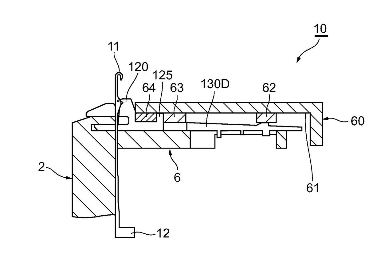
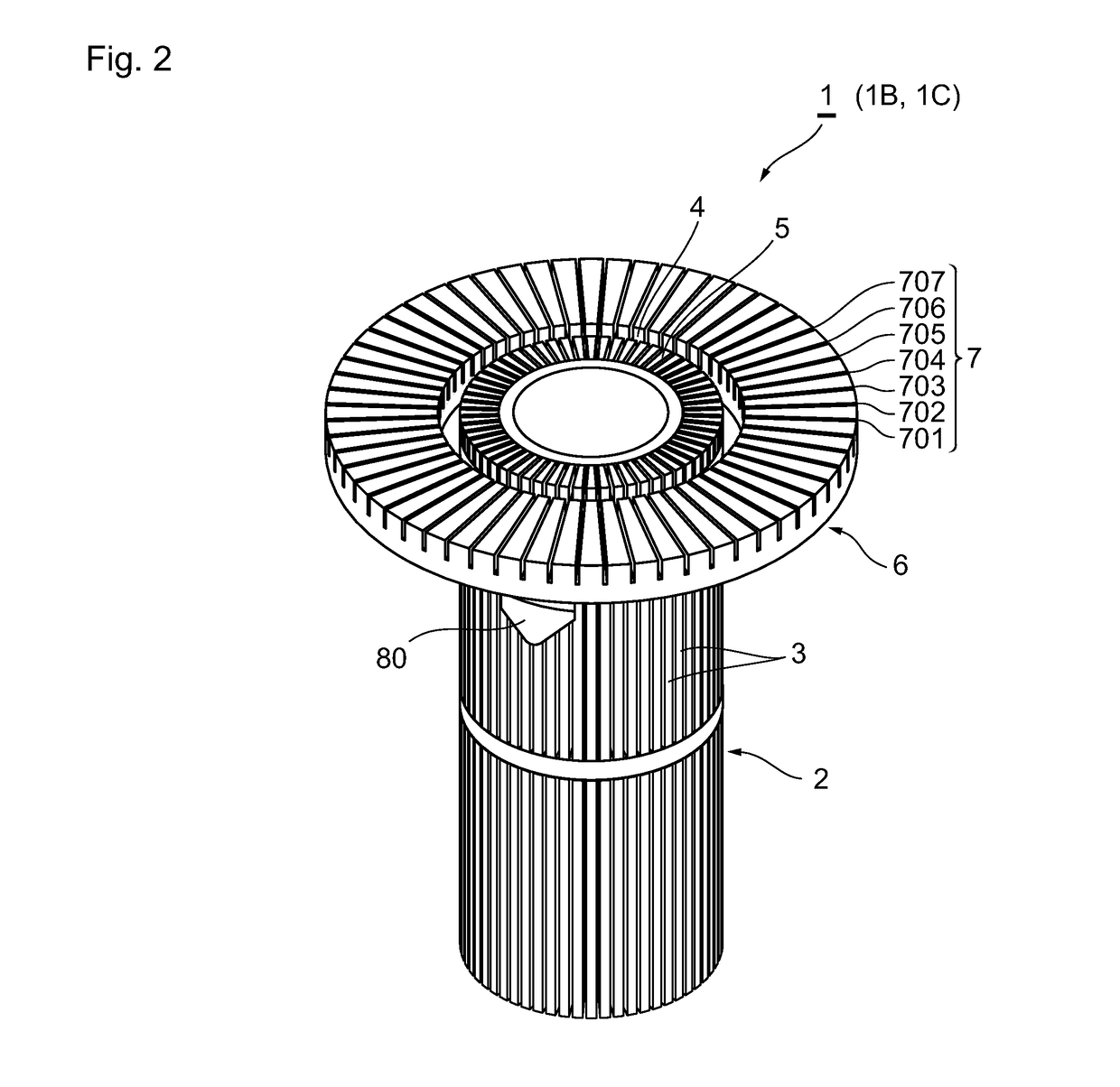
[0079]The circular knitting machine 1 of the first preferred embodiment is now described, referring to FIGS. 2 to 14B. FIG. 2 is an enlarged perspective view of ...

second preferred embodiment

[0127]Next, a circular knitting machine according to the second preferred embodiment of the present invention is described. The same description as that of the first preferred embodiment is omitted. The circular knitting machine of the second preferred embodiment can form stitches of three different sizes.

[0128]Hereinafter, differences between the first preferred embodiment and the second preferred embodiment are mainly described. The circular knitting machine 1B of the second preferred embodiment includes a stitch size controlling sinker 120B shown in FIG. 16 configured to form stitches of three different sizes, in place of the stitch size controlling sinker 120 shown in FIG. 3 that forms stitches of two different sizes. Also, the circular knitting machine of this preferred embodiment includes selector jacks 230 shown in FIGS. 18A to 18C in place of the selector jacks 130 shown in FIGS. 5A to 5F. Please note that three selector jacks 230 define one group in this preferred embodimen...

third preferred embodiment

[0171]Next, a circular knitting machine according to the third preferred embodiment of the present invention is described. The same description as that of the first preferred embodiment is omitted. The circular knitting machine of the third preferred embodiment is a multi-pile knitting machine which can provide different pile lengths of stitches and, more specifically, can form knit fabric in which three types of knitting structures including a plain stitch, a high-pile stitch, and a low-pile stitch are selectively arranged on a stitch-by-stitch basis.

[0172]FIG. 32 shows exemplary knitting structures which can be formed by the circular knitting machine of this preferred embodiment. The knitting structure in which pile yarn 91 and ground yarn 92 are knitted together and the sinker-loop lengths of the pile yarn 91 and the ground yarn 92 are the same is called a plain stitch 110; the knitting structure in which the sinker loop of the pile yarn 91 is longer than that of the ground yarn ...


PUM


Abstract

A circular knitting machine includes sinkers and selector jacks corresponding thereto that are provided as separate components. The selector jacks are arranged radially outside the sinkers, and are provided with selector butts such that the selector butts of circumferentially adjacent selector jacks are arranged at different radial positions. An actuator that acts on the selector butts is arranged radially outside the cylinder. The circular knitting machine prevents a failure of sinker selection, while increasing a rotation speed of a cylinder holding knitting needles.

Description

BACKGROUND OF THE INVENTION[0001]1. Field of the Invention[0002]The present invention relates to a stitch size controllable knitting machine for forming a knitted fabric by taking in and out sinkers to / from between reciprocating knitting needles, and to a manufacturing method of knitted fabric.[0003]2. Description of the Related Art[0004]A conventional circular knitting machine or hosiery circular knitting machine includes a stitch size controlling sinker, as described in JP 2004-316000A, for example. FIGS. 31A and 31B show an exemplary conventional stitch size controlling sinker and an actuator, respectively. Referring to FIG. 31A, each stitch size controlling sinker 201 has one of a plurality of selector butts 202 to 205 which can be pressed when the corresponding stitch size controlling sinker 201 is selected. In the example of FIG. 31A, four selector butts 202 to 205 are arranged at different levels in a height direction of the knitting machine. That is, the selector butts 202-2...

Claims


Application Information

Patent Timeline
Patent Type & Authority Patents(United States)
IPC IPC(8): D04B9/46D04B15/34D04B15/78D04B9/02D04B15/06
CPCD04B9/46D04B9/02D04B15/78D04B15/34D04B15/06D04B1/22D04B9/42
Inventor FUKUI, TAKAO
Owner OKAMOTO INDS
Features
  • R&D
  • Intellectual Property
  • Life Sciences
  • Materials
  • Tech Scout
  • Unparalleled Data Quality
  • Higher Quality Content
  • 60% Fewer Hallucinations
Learn More