Data staging management system

a data staging and management system technology, applied in the field of data staging, can solve the problems of low machine efficiency, waste of electrical power, and inefficient use of computing resources, and achieve the effect of improving resource usage and improving low machine efficiency

Active Publication Date: 2018-07-03
FUJITSU LTD
View PDF12 Cites 2 Cited by
  • Summary
  • Abstract
  • Description
  • Claims
  • Application Information

AI Technical Summary

Benefits of technology

[0082]Thus, embodiments of the present invention provide a data staging management system (DSMS) which improves low machine efficiency, segregating computation and pre- or post-processing to copy input and output data to improve resource usage. Computing resource allocation and data staging are done with reference to job status information.

Problems solved by technology

However, it is often the case that end users with applications (or “jobs”) to be executed, have to wait for a long time to acquire the necessary computing resources (“resources” here denoting CPUs, cores, memory and so forth), which means that computing resources are not efficiently used.
One of the major problems causing this issue is a process called “data staging”.
However, the data staging processes carried out before and after solver job execution take a lot of time, leaving computing resources almost idle, which causes low machine efficiency and wastes electrical power.
Because the data staging is carried out after securing the necessary computing resource, the time for I / O processing (stage-in) increases as the target data size increases, which causes inefficient use of the computing resource.
However, the following problems still exist.
Firstly, whilst a user waits for a job to be executed, there is the possibility that he / she changes the input data.
In the case of asynchronous data staging, because it is difficult for a user to know the start-time of the input data staging, changing the input data during this waiting period is impossible.
Secondly, if input data staging is scheduled using a first-in-first-out algorithm, the time taken for data staging increases and the allocation of compute nodes gets stacked as the amount of staging data increases.
These problems arise both during stage-in and stage-out.

Method used


Image

  • Data staging management system
  • Data staging management system
  • Data staging management system

Examples


Embodiment Construction

[0093]Reference will now be made in detail to the embodiments, examples of which are illustrated in the accompanying drawings, wherein like reference numerals refer to the like elements throughout. The embodiments are described below to explain the present invention by referring to the figures.

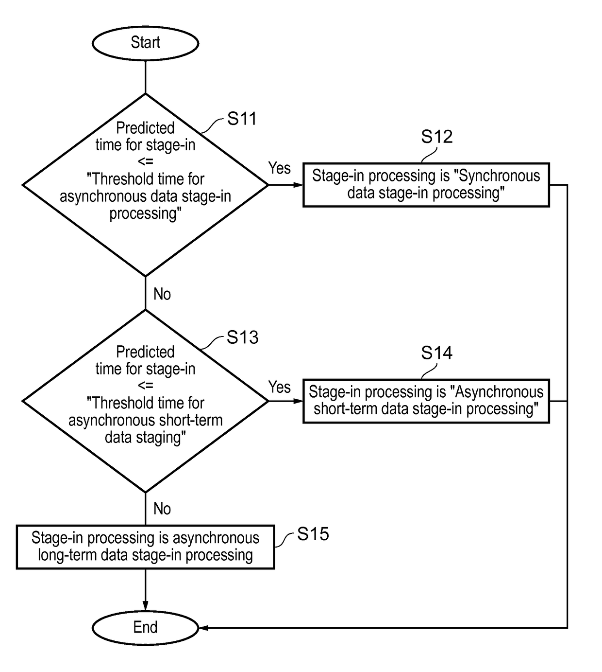
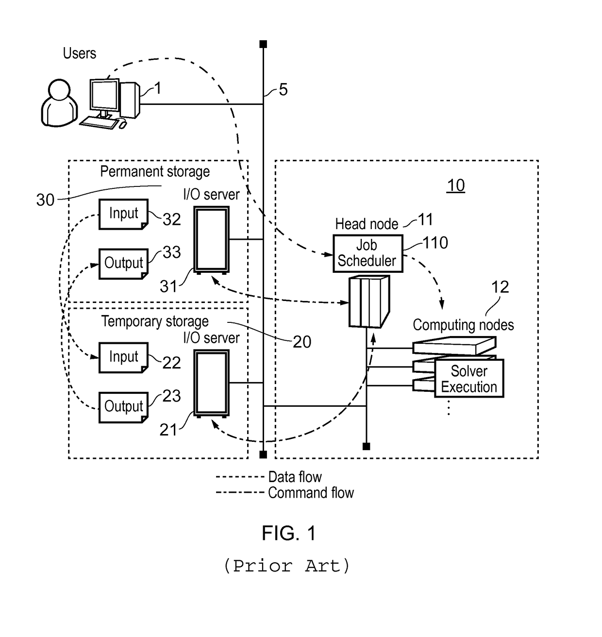
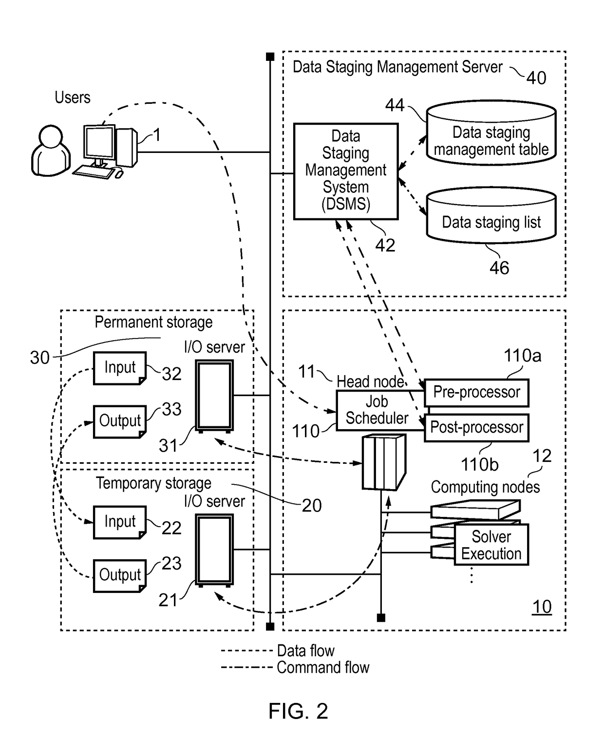
[0094]As mentioned in the introduction, when input data staging is carried out, computing resources are reserved for the corresponding job even though they are not being used for computing. Subsequent jobs in the queue must wait for earlier jobs to complete their data staging, even if a subsequent job has relatively modest data staging requirements. This makes occupied resources almost idle and brings about low resource usage. Also in output data staging, the same situation happens. Because the amount of transferred data may be huge, it takes a long time before a job starts to run, and occupied resources are held by the job until data staging is completed. To address this problem, embodiments ...


PUM


Abstract

Batch job data staging combining synchronous / asynchronous staging. In pre-processing, a stage-in source file, and a target file for stage-out, in permanent storage, are identified using a batch script. From data amounts, time for stage-in / stage-out to / from temporary storage are estimated. Stage-in is based on the time, stage-out being asynchronous, and each asynchronous staging is classified short / long term depending on the time, each staging being recorded in a table. If a source file is modified, incremental staging is added to the table. With a staging list scheduling for batch jobs stage-in is performed, monitoring progress in the table, and resources may be allocated for the jobs nodes without waiting for stage-in to complete. The job generates results in the temporary storage, and using post-processing, stage-out transfers results to the target file in permanent storage.

Description

CROSS-REFERENCE TO RELATED APPLICATIONS[0001]This application claims the benefit of European Application No. 14192070.2, filed Nov. 6, 2014, in the U.S. Intellectual Property Office, the disclosure of which is incorporated herein by reference.BACKGROUND[0002]1. Field[0003]The present invention relates to data staging between temporary storage and permanent storage, particularly but not necessarily exclusively in high-performance computing (HPC) systems. More particularly, the present invention provides a data staging management system and a method of managing data staging in a computer system.[0004]2. Description of the Related Art[0005]HPC systems or clusters are widely used nowadays for computer simulation in various fields. However, it is often the case that end users with applications (or “jobs”) to be executed, have to wait for a long time to acquire the necessary computing resources (“resources” here denoting CPUs, cores, memory and so forth), which means that computing resour...

Claims


Application Information

Patent Timeline
Patent Type & Authority Patents(United States)
IPC IPC(8): G06F9/46G06F9/48G06F9/50
CPCG06F9/5038G06F9/4843G06F9/5016
Inventor KURAISHI, HIDEAKIISHISAKA, AKIRA
Owner FUJITSU LTD
Why Eureka
Try Eureka