
Position detecting device and projector

Active Publication Date: 2018-07-10
CASIO COMPUTER CO LTD
View PDF3 Cites 0 Cited by
  • Summary
  • Abstract
  • Description
  • Claims
  • Application Information

AI Technical Summary

Benefits of technology

The present invention provides a position detecting device and a projector. The device includes a light emission unit, a polarization filter, and an imaging unit that can emit light in a certain wavelength band and capture the reflected light from the surface of an object. The device can also block out other wavelength bands of light. The projector includes a position detecting device and a projection unit that can project light in a different wavelength band. An associating unit can correlate the position of the projected light with the position of the detected object. These invention devices can help accurately detect and locate objects on a surface.

Problems solved by technology

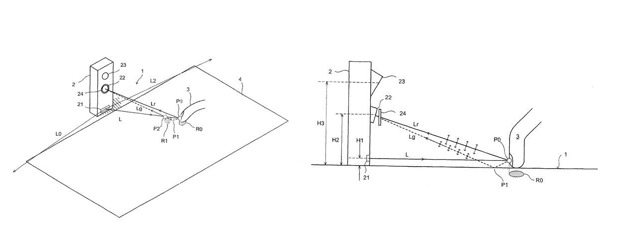
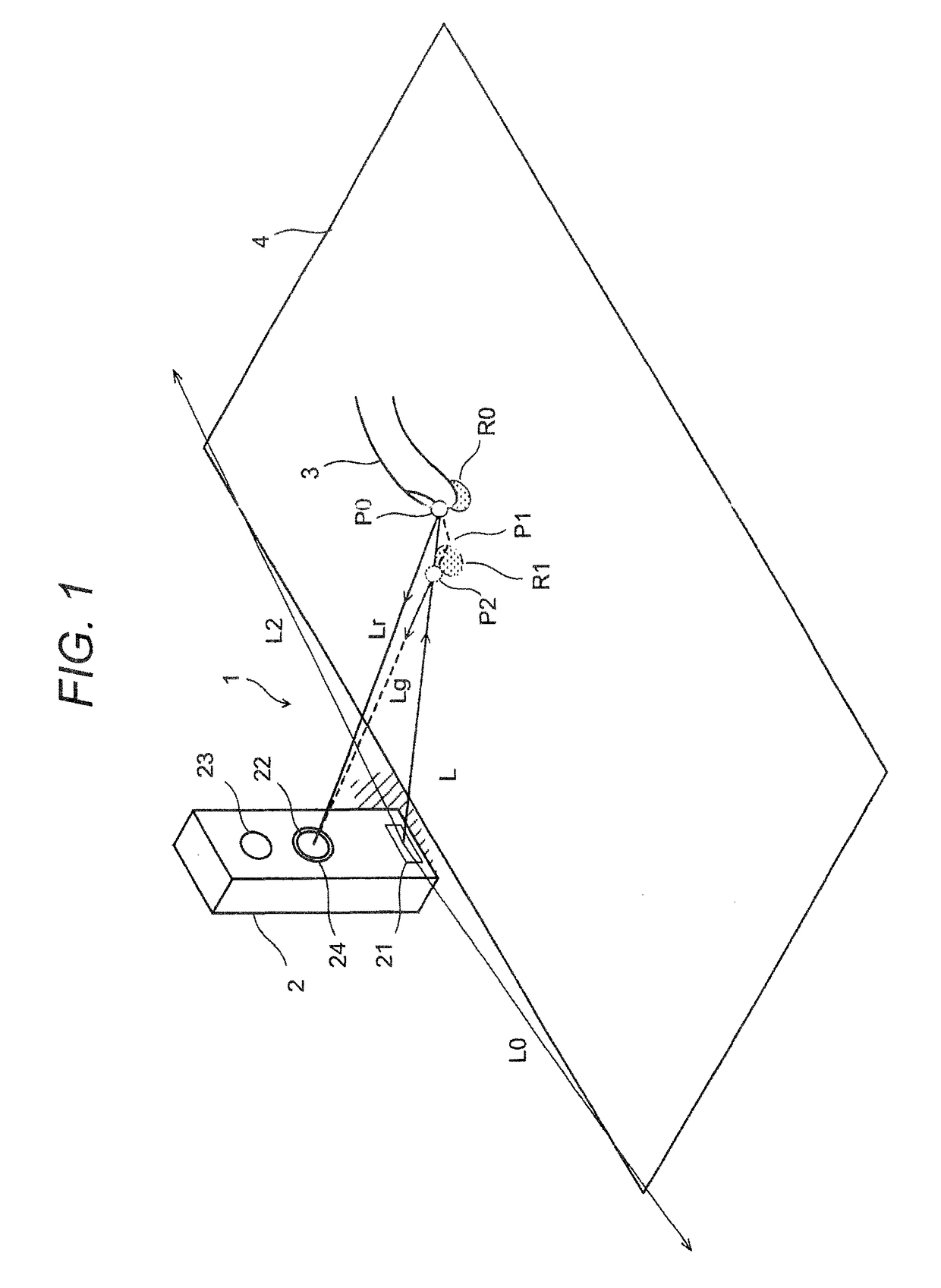
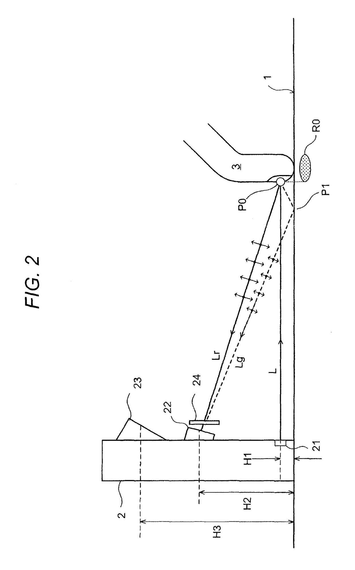
However, when the desk 1 is glossy and reflection intensity thereof is high, in a case where intensity of an unnecessary light beam passing through the wrong optical path Lg exceeds a threshold, it is determined that there is a pseudo light blocking point P2 and a wrong touch position R1 is erroneously recognized.

Method used


Image

  • Position detecting device and projector
  • Position detecting device and projector
  • Position detecting device and projector

Examples


modification example

[0041]The present invention is not limited to the above embodiments and can be modified within the spirit and the scope of the present invention. There are, for example, the following (a) to (g).

[0042](a) In each of the first and second embodiments, the fan-shaped IR emission unit 21 not necessarily emits infrared light and may emit ultraviolet light.

[0043](b) Instead of emission of infrared light in a fan-shaped manner similarly to the above embodiments, scanning with beam-shaped infrared light may be performed in a fan-shaped manner to detect an operation region. Also, a plurality of light sources of parallel infrared light may be provided linearly to detect an operation region. There is no limitation.

[0044](c) The projection unit 23 of each of the first and second embodiments may project a red laser beam or the like instead of visible light. Light emitted by the fan-shaped IR emission unit 21 may be light in a wavelength band different from that of light projected by the projecti...


PUM


Abstract

Provided is a position detecting device including: a light emission unit configured to emit light in a predetermined wavelength band in a manner substantially parallel to a plane surface; a polarization filter configured to transmit p polarized light of light reflected on the plane surface and to block s polarized light thereof; and an imaging unit configured to perform imaging of the plane surface obliquely from above with the light in the predetermined wavelength band through the polarization filter.

Description

BACKGROUND OF THE INVENTION[0001]Field of the Invention[0002]An embodiment of the present invention relates to a position detecting device, and a projector having a position detecting function.[0003]Description of the Related Art[0004]Recently, a projector having an interactive function with which it is possible to input a position on a projected screen has appeared. This projector can not only project an image but also input positional information in real time with touch operation. Accordingly, it is possible to input operation information (positional information) only with a touch on a projection screen without operation of a mouse and to easily realize an electronic blackboard function. That is, it is possible to provide a projection screen of a projector as a pseudo touch panel on which operation or writing can be performed with a direct touch.[0005]Similarly, there is a product called a laser keyboard with which it is possible to perform a key input by projection of a keyboard ...

Claims


Application Information

Patent Timeline
Patent Type & Authority Patents(United States)
IPC IPC(8): G06F3/042G06F3/041
CPCG06F3/0418G06F3/0425G06F3/042
Inventor INOUE, HIDEAKI
Owner CASIO COMPUTER CO LTD
Learn More