Panel mount system

a technology of mounting system and panel, which is applied in the direction of sheets/panels, mechanical equipment, swimming pools, etc., can solve the problems of difficult and time-consuming drilling, difficult and time-consuming to drill, and difficult post production workability of such glass

Active Publication Date: 2018-07-24
GLASS VICE HLDG
View PDF26 Cites 5 Cited by
  • Summary
  • Abstract
  • Description
  • Claims
  • Application Information

AI Technical Summary

Benefits of technology

[0034]In some embodiments a primary threaded member of each intermediate clamping member facilitates a lateral movement of its respective intermediate clamping member relative its respective clamp jaw, the primary threaded members configured to, upon the lateral movement of at least one of the intermediate clamping members to clamp a panel between the intermediate clamping members, form a pivot for the panel relative to the clamp jaws, and
[0209]Preferably the height of the screws of each panel mount in the partition system can be adjusted to compensate for any misalignment in the height of the panel mounts such that the protective cover is level.

Problems solved by technology

Post production workability of such glass can be difficult.
Mounting of such glass panes can be cumbersome.
They can be difficult and time consuming to drill.
While these devices provide adequate support to glass panes and are adjustable to some degree, they do have some limitations.
For this reason, these devices can obscure the view through the glass somewhat, and may be considered unsightly.

Method used


Image

  • Panel mount system
  • Panel mount system
  • Panel mount system

Examples


Embodiment Construction

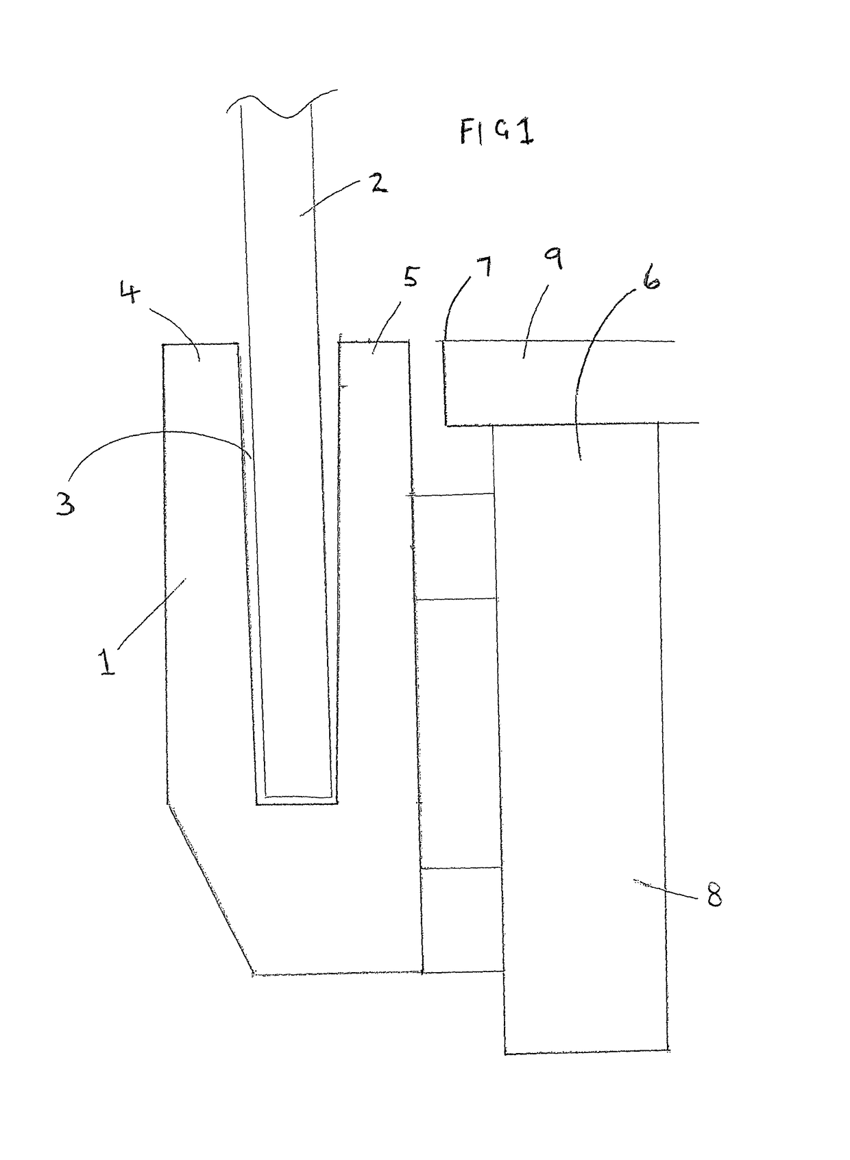
[0311]With reference to FIG. 1 there is shown a panel mount 1 for mounting a panel 2. The panel 2 is received in the slot 3 which is defined by first and second clamp jaws 4 and 5 respectively. The panel 2 is preferably a glass pane, but may be any other type of panel made from any material.

[0312]The panel mount 1 is shown mounted to the side of a structure 6 such that the top extent of the panel mount 1 does not extend beyond the top edge 7 of the structure 6. In some applications it may be desirable for the panel mount 1 to be located in such a manner so that it is at least partially obscured from view for a person located on the structure. The lower the panel mount 1 is below the edge 7, the more it will be obscured from view for a person located on the structure. When the panel mount is located below the edge 7, the panel 1 can extend above the edge and, if the panel is glass, a person located on the structure will have an unobscured view through the glass. This may be particula...


PUM


Abstract

A panel mount for non penetrative fastening of a panel (such as a glass pane) able to be mounted to a structure, and preferably to a vertical or side surface of that structure, which provides a pair of clamp jaws defining an elongate slot in which an edge of a panel can be received and an intermediate clamping member associated with each jaw, each intermediate clamping member having at least one threaded member associated therewith to facilitate adjustment of the position and orientation of the intermediate member within the clamp jaw so as to securely retain the panel within the slot.

Description

CROSS REFERENCE TO RELATED APPLICATIONS[0001]This is a U.S. National Phase patent application of International Application No. PCT / IB2012 / 056034, filed Oct. 31, 2012, which claims priority to New Zealand Patent Application No. 596115 filed on Oct. 31, 2011, New Zealand Patent Application No. 597778 filed on Jan. 24, 2012, and New Zealand Patent Application No. 599765 filed on May 3, 2012, each of which is hereby incorporated by reference in the present disclosure in its entirety.FIELD OF THE INVENTION[0002]The present invention relates to panel mounts for the mounting of panels such as glass panes.BACKGROUND[0003]Glass panes are used in buildings for many purposes. Glass panes can offer partitions within offices, showers, as a guard rail around an edge with a drop off, as fencing for a pool and the like.[0004]Such glass panes are normally of a reinforced glass that has substantial impact or break resistance. Post production workability of such glass can be difficult.[0005]Mounting o...

Claims


Application Information

Patent Timeline
Patent Type & Authority Patents(United States)
IPC IPC(8): F16B2/12E04C1/42E04F11/18E04H4/06E04H17/16
CPCF16B2/12E04C1/42E04F11/1812E04H4/06E04H17/16E04F11/1853Y10T403/7067E04F11/1817E04H17/22E04F2011/1823F16S1/02
Inventor ALLEN, WARWICK JAMES
Owner GLASS VICE HLDG
Why Eureka
Try Eureka