Connector

a technology of connecting parts and connectors, applied in the direction of coupling contact members, coupling device connections, electrical apparatus, etc., can solve the problems of deteriorating connection reliability between the first terminal and the short-circuit terminal, and the increase of the manufacturing cost of the connector, so as to reduce the enlarging of sliding parts and suppress the effect of enlarging the sliding parts

Active Publication Date: 2018-07-24
YAZAKI CORP
View PDF10 Cites 3 Cited by
  • Summary
  • Abstract
  • Description
  • Claims
  • Application Information

AI Technical Summary

Benefits of technology

[0010]In the conventional connector, therefore, gold-plating films are formed on respective contact surfaces of the first terminal and the contact pieces coming into contact each other in order to reduce the contact load of the contact pieces while ensuring the connection reliability. However, the formation of such gold-plating films is so expensive as to cause the manufacturing cost of the connector to be elevated.
[0011]Therefore, it is an object of the present application to provide a connector which is capable of reducing manufacturing cost while maintaining connection reliability between first terminals and a short-circuit terminal.
[0013]Although the manufacturing cost could be saved in comparison with a connector having gold-plating films formed on the contact surfaces due to the formation of the tin plating films, the contact surfaces of the first terminal and the contact pieces would be formed with oxide films which increase their contact resistances.
[0015]In the connector according to the aspect of the present application, therefore, even if forming inexpensive tin-plating films on the contact surfaces of the first terminals and the contact pieces while reducing the contact loads of the contact pieces, the oxide films could be removed by the slide movements of the contact pieces and the first terminals by the sliding parts, thereby allowing the manufacturing cost to be reduced while maintaining the connection reliability between the first terminals and the shirt-circuit terminals.
[0017]In such an arrangement that each of the sliding parts is positioned between the pair of contact pieces of corresponding short-circuit terminal, it is possible to suppress the enlarging of the sliding parts since two contact pieces can be displaced by a single sliding part.
[0018]With the connector according to the aspect of the present application, it is possible to reduce the manufacturing cost while maintaining the connection reliability between the first terminals and the short circuit terminal.

Problems solved by technology

However, if the contact load of the contact pieces is reduced, there arises a possibility that the connection reliability between the first terminals and the short-circuit terminal is deteriorated.
However, the formation of such gold-plating films is so expensive as to cause the manufacturing cost of the connector to be elevated.

Method used


Image

  • Connector
  • Connector
  • Connector

Examples


Embodiment Construction

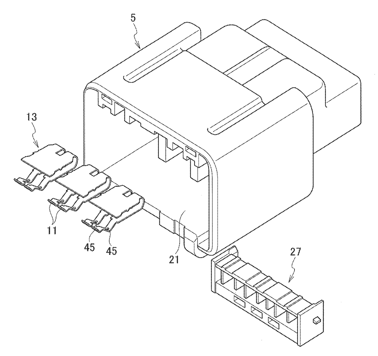
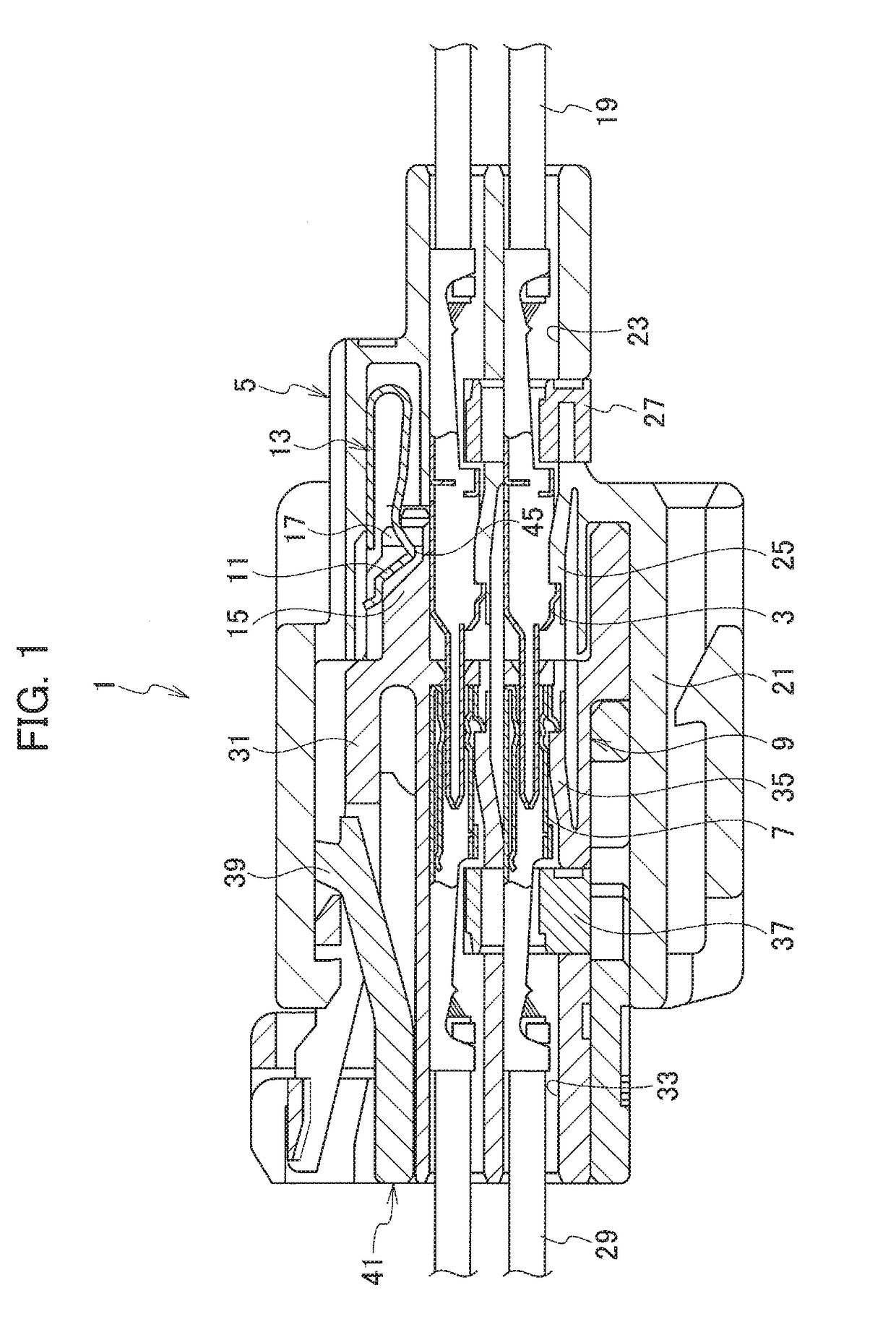
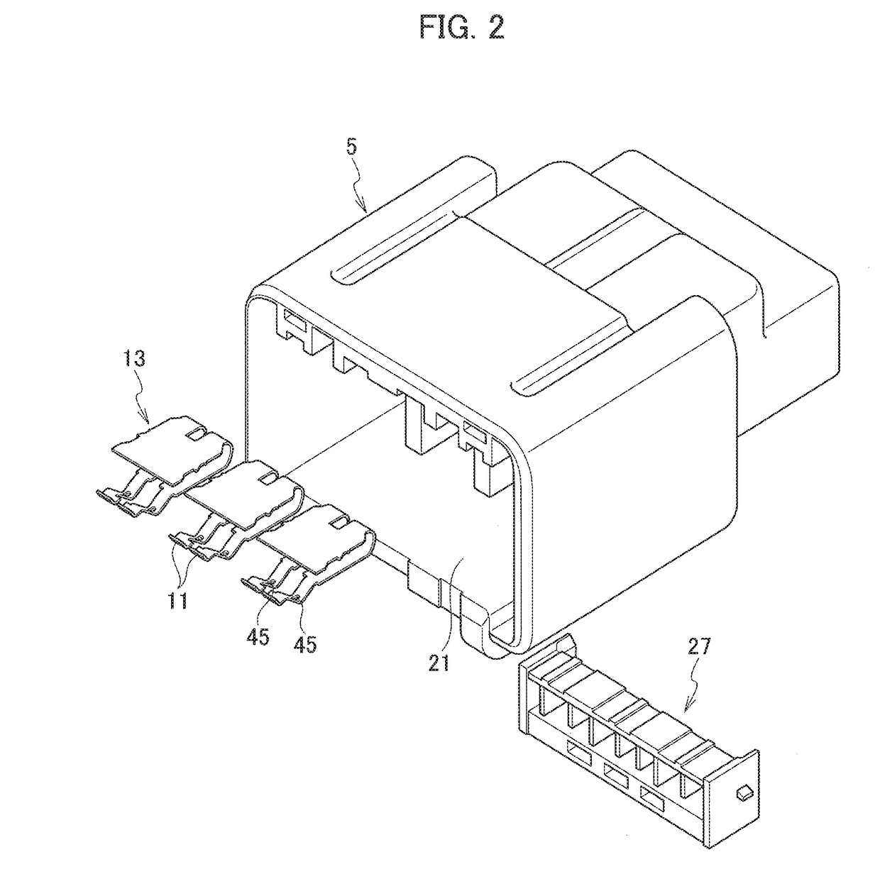
[0030]A connector according to an embodiment will be described with reference to FIGS. 1 to 10.

[0031]The connector 1 according to the embodiment includes a first housing 5 accommodating a plurality of first terminals 3, a second housing 9 which accommodates a plurality of second terminals 7 connectable to the first terminals 3 and which is fittable to the first housing 5, short-circuit terminals 13 accommodated in the first housing 5 each having contact pieces 11, 11 coming into contact with adjacent first terminals 3, 3, and releasing parts 15 provided in the second housing 9 to displace the contact pieces 11 for releasing the contacts between the first terminals 3 and the contact pieces 11.

[0032]Tin-plating films are formed on respective contact surfaces of the first terminal 3 and the contact pieces 11, which come into contact with each other. The second housing 9 is provided with sliding parts 17 which are disposed on the front side of each of the releasing parts 15 in the fitti...


PUM


Abstract

A connector includes a first housing accommodating first terminals, a second housing accommodating second terminals connectable to the first terminals and fittable to the first housing, short-circuit terminals accommodated in the first housing and each having a pair of contact pieces that respectively come in contact with corresponding first terminals adjacent to each other, releasing parts provided in the second housing and configured so as to displace the contact pieces, thereby releasing contacts between the first terminals and the contact pieces, tin plating films formed on respective contact surfaces of the first terminals and the contact pieces coming into contact with each other, and sliding parts provided in the second housing and positioned ahead of the releasing parts in a fitting direction between the first housing and the second housing to displace the contact pieces thereby allowing the contact pieces to slide on the first terminals.

Description

CROSS REFERENCE TO RELATED APPLICATION[0001]The present application is based on, and claims priority from Japanese Patent Application No. 2016-149191, filed Jul. 29, 2016, the disclosure of which is hereby incorporated by reference herein in its entirety.TECHNICAL FIELD[0002]The present application relates to a connector, and more specifically to a connector having a short-circuit terminal connecting among a plurality of terminals accommodated in a housing.BACKGROUND ART[0003]As a conventional connector, there is known a connector that includes a first housing accommodating female terminals as a plurality of first terminals, a second housing which is fittable to the first housing and which accommodates male terminals as a plurality of second terminals connectable to the female terminals, a short-circuit terminal accommodated in the first housing to have contact pieces in contact with the adjacent female terminals, and releasing pieces provided in the second housing to displace the c...

Claims


Application Information

Patent Timeline
Patent Type & Authority Patents(United States)
IPC IPC(8): H01R13/28H01R13/24H01R9/03H01R13/703H01R13/436H01R13/422
CPCH01R13/28H01R9/03H01R13/2464H01R13/4365H01R13/7031H01R13/4223H01R13/71H01R31/08H01R13/03H01R13/7032
Inventor SEKINO, TETSUYASAKAMOTO, NOBUYUKIYAMAMOTO, TOSHINORI
Owner YAZAKI CORP
Why Eureka
Try Eureka