Gas turbine with two swirl supply lines for cooling the rotor

a technology of supply line and rotor cooling, which is applied in the direction of gas turbine plants, machines/engines, engine fuctions, etc., can solve the problems of forming dead spaces, affecting the cooling effect of the rotor, and requiring a large amount of energy. , to achieve the effect of high technical expenditur

Inactive Publication Date: 2018-07-31
SIEMENS ENERGY GLOBAL GMBH & CO KG
View PDF16 Cites 4 Cited by
  • Summary
  • Abstract
  • Description
  • Claims
  • Application Information

AI Technical Summary

Benefits of technology

[0008]In association with these disadvantages from the prior art, the technical requirement therefore arises to propose a gas turbine which can avoid the disadvantages which are known from the prior art. In particular, the gas turbine which is to be proposed is to enable an advantageous cooling of the components which delimit the annulus but without requiring high technical outlay. Above all, dead spaces in the annulus, which give cause to different cooling rates in certain areas, are to be avoided.

Problems solved by technology

For the transfer of the cooling fluid into the relevant discharge lines of the rotor it is necessary, however, that the transfer effort or entry effort at the discharge line opening is as little as possible.
A disadvantage of this embodiment which is known from the prior art, however, is first of all a considerably higher technical cost since the bypass line has to be built into internal casing parts of the gas turbine.
Furthermore, in the case of the solution which is known from the prior art, there is also the occurrence of dead spaces which are formed between the first and second swirl supply lines and in which the rotor cooling is in the first instance carried out by convective transportation of the cooling fluid.
This, however, ensures an only unsatisfactory cooling in the sections of the rotor which delimit the dead spaces, and therefore leads to high heating of the rotor in certain areas which, however, it is necessary to avoid.

Method used


Image

  • Gas turbine with two swirl supply lines for cooling the rotor
  • Gas turbine with two swirl supply lines for cooling the rotor

Examples


Embodiment Construction

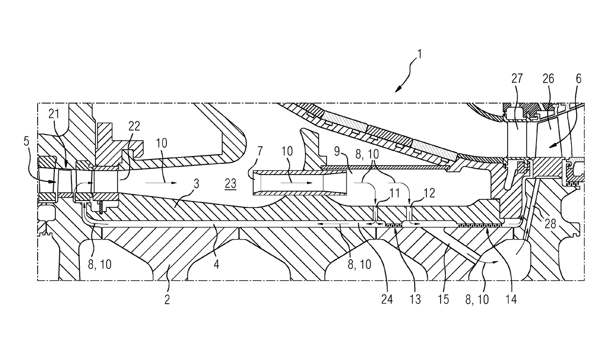
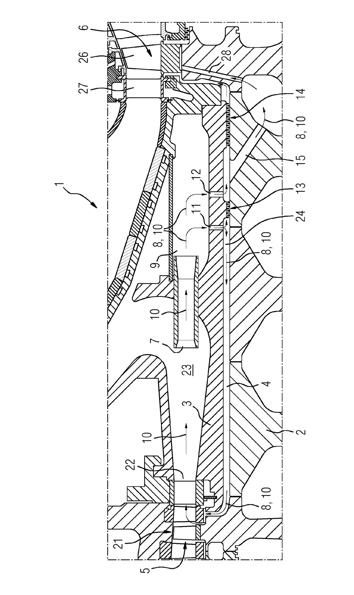
[0032]The present FIGURE shows a cross-sectional view in the longitudinal direction along the annulus 4 of a gas turbine 1 according to the invention. The annulus 4 is in this case delimited at the ends by a compressor section 5 and also by an expansion turbine section 6 respectively and is arranged between an inner casing part 3, which is typically formed as a shaft cover, and the rotor 2. The components of the rotor 2, which include compressor rotor blades 21, execute a rotational movement during operation of the gas turbine 1 so that these move in relation to the static inner casing part 3 (out of the plane of the paper or into this).

[0033]On account of the high temperatures which prevail in this region, cooling of the inner casing part 3 and also of the rotor 2 is necessary in order to be able to correspondingly dissipate the heat in these regions. The cooling is undertaken by means of a cooling fluid 8 which in the present case is compressor air 10, wherein the compressor air 1...


PUM


Abstract

A gas turbine has at least one rotor and inner housing part to form an annular chamber therebetween. The annular chamber is fluidically connected to a compressor portion at one end and expansion turbine portion at the other, and is supplied with cooling fluid. First and second swirl supply lines supply the annular chamber with cooling fluid. The cooling fluid is supplied to the surface of the rotor with a tangential flow component, and a first seal element in the annular chamber acts as a flow resistor. A discharge line in the rotor between the first seal element and expansion turbine portion receives and discharges cooling fluid from the second swirl supply line. No bypass lines are provided from the first swirl supply line such that the cooling fluid is conducted around the second swirl supply line in order to be returned to a location of the annular chamber.

Description

CROSS REFERENCE TO RELATED APPLICATIONS[0001]This application is the U.S. National Stage of International Application No. PCT / EP2015 / 072709 filed Oct. 1, 2015, and claims the benefit thereof. The International Application claims the benefit of Oct. 7, 2014 Application No. EP14187954 filed Oct. 7, 2014. All of the applications are incorporated by reference herein in their entirety.FIELD OF INVENTION[0002]The present invention relates to a gas turbine having at least one rotor and also an inner casing part for forming an annulus between rotor and inner casing part, wherein the annulus is designed for being supplied with a cooling fluid which allows the rotor to be cooled during operation of the gas turbine.BACKGROUND OF INVENTION[0003]On account of the high gas temperatures during the combustion operation in a gas turbine, it is necessary for numerous functional components to be suitably cooled. Particularly in the region of the center section of a gas turbine in which the hot gas fro...

Claims


Application Information

Patent Timeline
Patent Type & Authority Patents(United States)
IPC IPC(8): F01D5/08F02C9/18F01D25/12
CPCF01D5/081F01D5/084F01D5/087F02C9/18F01D25/12F05D2260/205F05D2260/20
Inventor KOWALSKI, CHRISTIANKRUTZFELDT, JOACHIM
Owner SIEMENS ENERGY GLOBAL GMBH & CO KG
Why Eureka
Try Eureka