Liquid dosing apparatus

a technology of liquid dosing apparatus and liquid dosing chamber, which is applied in the direction of liquid/fluent solid measurement, movable measuring chamber, instruments, etc., can solve the problems of increased costs and unnecessary materials, inconvenience of bulky apparatus, and repeated tilting of containers, and achieve constant dosing

Active Publication Date: 2018-08-14
PROCTER & GAMBLE CO
View PDF17 Cites 1 Cited by
  • Summary
  • Abstract
  • Description
  • Claims
  • Application Information

AI Technical Summary

Benefits of technology

[0011]A further advantage of the present invention is that substantially constant dosage is achieved even when close to product depletion.
[0012]Other objects, features and advantages of the invention will be better understood with reference to the attached drawings and the specification hereinafter.SUMMARY OF THE INVENTION
[0013]A first aspect of the present invention is a dosing apparatus for dispensing a dose of liquid comprising a resiliently squeezable container, a cap operably connected to said container said cap comprising a nozzle, wherein said nozzle defines an orifice at its apex. A dosing chamber is operably connected to said cap, wherein said dosing chamber comprises a base having a discharge opening therein, sidewalls extending upwardly along the perimeter of said base and at least one inlet opening located proximal said sidewalls. At least one timer aperture is located proximal to said discharge opening. A plunger is provided in said dosing chamber and is moveable relative to said chamber so as to advance upon squeezing of said container, up to a blocking position. A valve retaining means is located below said base. A valve is provided in said retaining means wherein said valve is movable from an open position, allowing liquid flow through said discharge opening, and a closed position, where the valve blocks said discharge opening. Wherein, the ratio of the total surface of said inlet openings and said timer apertures is from 2 to 17, and wherein the viscosity of said liquid is from 1 to 600 mPa·s (measured at 10 s−1 at 20° C.).
[0014]A second aspect of the present invention is a method of dosing with an apparatus comprising a resiliently squeezable container, a cap operably connected to said container said cap comprising a nozzle, wherein said nozzle defines an orifice at its apex. A dosing chamber is operably connected to said cap, wherein said dosing chamber comprises a base having a discharge opening therein, sidewalls extending upwardly along the perimeter of said base and at least one inlet opening located proximal said sidewalls. At least one timer aperture is located proximal to said discharge opening. A plunger is provided in said dosing chamber and is moveable relative to said chamber so as to advance upon squeezing of said container, up to a blocking position. A valve retaining means is located below said base. A valve is provided in said retaining means wherein said valve is movable from an open position, allowing liquid flow through said discharge opening, and a closed position, where the valve blocks said discharge opening. Said method comprising the steps of; orienting said apparatus top down; squeezing said container to generate a pressure of from 2 kPa to 12 kPa, for no more than 1.5 seconds, preferably no more than one second, to complete the dose; releasing the force from said container to permit said valve to open, release said liquid from said dosage chamber via said discharge opening and allow said plunger to return to its starting position; and optionally, squeezing again to begin a second dose without inverting said container.

Problems solved by technology

A number of disadvantages are introduced by such an arrangement that will be apparent to the person skilled in the art.
For example such arrangement implies a bulky construction, particularly when larger doses are required.
Thus, manufacturing complexity is introduced leading to increased costs and unnecessary materials being used.
Furthermore, the user is faced with the inconvenience of a bulky apparatus and the need for repeated tilting of the container for obtaining a dosed amount of liquid.
A disadvantage of such a system is the requirement of repeated tilting of the device between upright and inverted positions for multiple dosage.
A further disadvantage is the dependency of the given dose on the volume of the measuring tube, thus introducing limitations as to compactness.
Moreover, accuracy of dosage may be affected by any amount of liquid being sucked back into the container via the fluid passage conduit upon release of pressure.
However, such arrangement still requires tilting the device upside down and upright for each dosage.
However, such arrangement introduces disadvantages such as increased number of parts and jamming of the obturator following discharge of the liquid caused by left-behind residue accumulating at the bottom of the control chamber that subsequently dries up.
This in turn may affect the consistency of the dosage.

Method used


Image

  • Liquid dosing apparatus
  • Liquid dosing apparatus
  • Liquid dosing apparatus

Examples


Embodiment Construction

[0030]By the terms “a” and “an” when describing a particular element, we herein mean “at least one” of that particular element.

[0031]The term “dose” as used herein is defined as the measured amount of liquid to be delivered by the apparatus. The dose begins when the liquid first exits the nozzle and ends once the flow of said liquid stops.

[0032]By “substantially independently from pressure” as used herein it is meant that pressure causes less than 10% variation from the target measured dose.

[0033]By “substantially constant liquid output or dosage” as used herein it is meant that variation from the target measured dose is less than 10%.

[0034]By “resiliently squeezable” as used herein it is meant that the container returns to its original shape without suffering any permanent deformation once pressure is released therefrom.

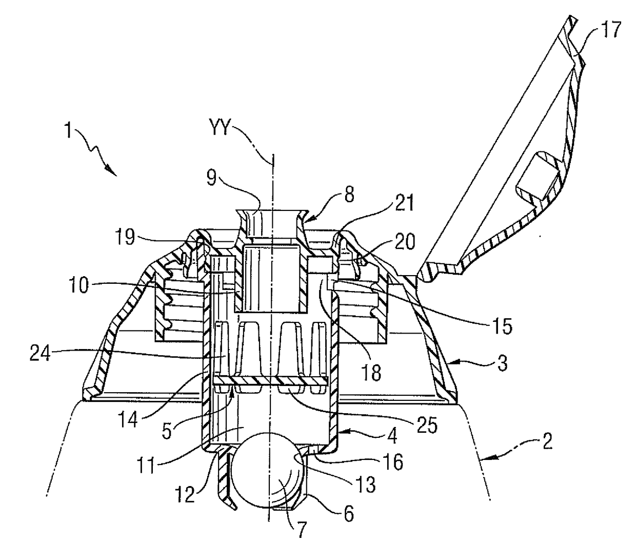
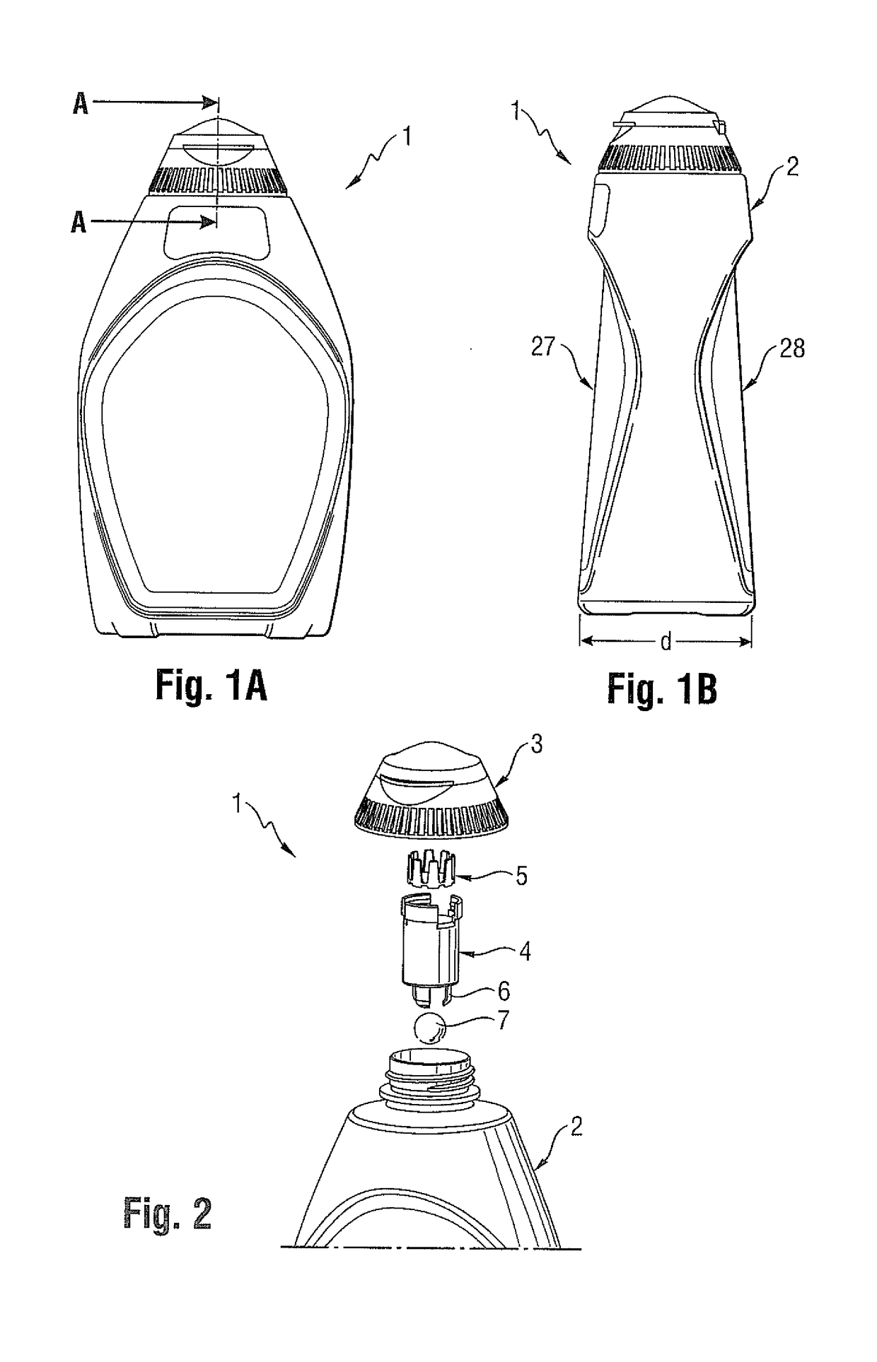
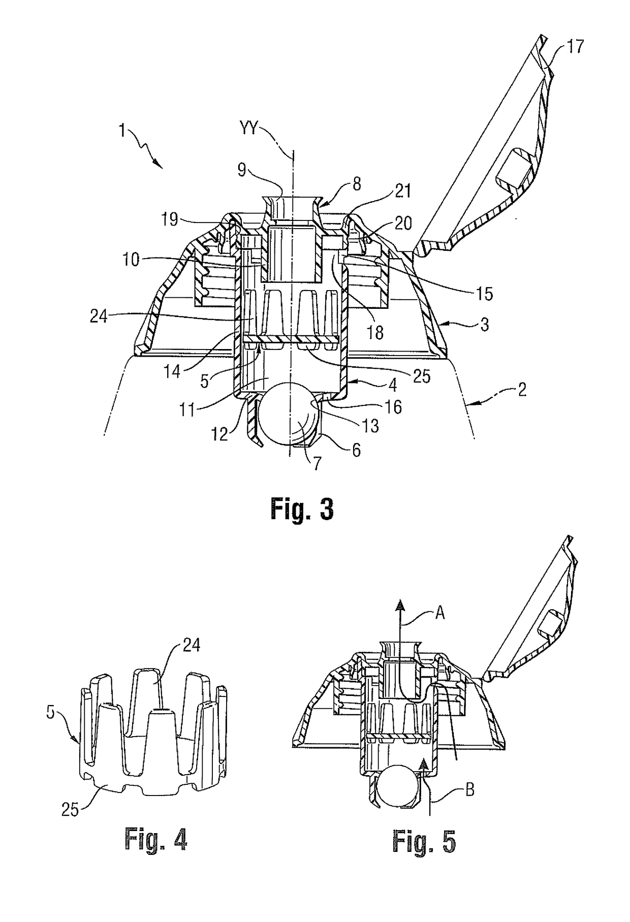
[0035]The invention is directed to an apparatus (1) for repeatedly dosing a quantity of liquid. The apparatus (1) comprises a resiliently squeezable container (2), ...


PUM


Abstract

The present invention relates to an apparatus and methods of repeatedly dispensing controlled doses of liquid. In one embodiment of the present invention, the apparatus includes a resiliently squeezable container, a cap operably connected to the container, a dosing chamber operably connected to the cap, at least one timer aperture located proximal to the discharge opening, a plunger, a valve retaining means located below the base, and a valve provided in the valve retaining means. The ratio of the total surface of the inlet openings and the timer apertures is from about 2 to about 17 and the viscosity of the liquid is from about 1 to about 600 mPa·s (measured at 10 s−1 at 20° C.).

Description

FIELD OF INVENTION[0001]The present invention relates to an apparatus and means of repeatedly dispensing controlled doses of liquid. A preferred field of use is that of dosage devices for domestic or household use, containing detergents such as hard surface cleaning compositions or other cleaning preparations, fabric conditioners and the like. Other fields of use include dosage devices for manual and automatic dishwashing liquids, hair-care products and oral care applications such as mouth washes.BACKGROUND OF THE INVENTION[0002]It may be desirable to deliver repeated doses of liquid without requiring the recurring inversion of the container. It may also be desirable to provide a dosage system which does not rely solely on gravity for achieving said dosage. It may be particularly desirable to deliver said benefits whilst offering a compact and simple construction. This could be for a number of reasons, including flexibility and ease-of-use offered to the user, ease of manufacture, s...

Claims


Application Information

Patent Timeline
Patent Type & Authority Patents(United States)
IPC IPC(8): B65D47/00G01F11/26G01F11/04G01F11/28G01F13/00
CPCG01F13/006G01F11/04G01F11/286G01F11/265G01F11/263
Inventor HOEFTE, PAULUS ANTONIUS AUGUSTINUSBECK, WOLFRAMLAMBRIGTS, MIRANDA
Owner PROCTER & GAMBLE CO
Why Eureka
Try Eureka