Headrest greasing machine

An oiler and headrest technology, applied in mechanical equipment, engine components, engine lubrication, etc., can solve the problems of laborious insertion and removal, unable to guarantee the pulling force of products with oil consumption, easy to pollute the seat, etc., and achieve constant consumption. , Save labor hours, reduce the effect of oil mist leakage

Inactive Publication Date: 2016-04-06
YIZHENG YANFENG JOHNSON CONTROLS SEATING
View PDF0 Cites 2 Cited by
  • Summary
  • Abstract
  • Description
  • Claims
  • Application Information

AI Technical Summary

Problems solved by technology

[0002] The headrest of the seat is inserted into the upper end of the seat by two headrest guide rods. The headrest can be adjusted up and down. The adjustment force is strictly regulated as 10N-90N. Due to internal friction, plugging and unplugging is laborious, which exceeds the design standard
In order to ensure that the insertion force meets the standard requirements, it is often necessary to apply lubricating oil on the headrest guide rod during the assembly process. Generally, manual oiling is used, which cannot guarantee the amount of grease and the pulling force of the product. It needs to be carried out offline. Rework, if the amount of spray is too much, it is easy to contaminate the seat when the headrest is assembled

Method used


Image

  • Headrest greasing machine
  • Headrest greasing machine
  • Headrest greasing machine

Examples


Embodiment Construction

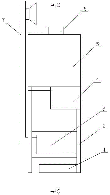
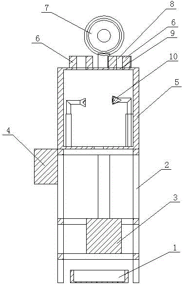
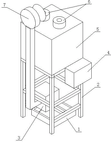
[0011] Such as figure 1 As shown in -3, it is a headrest oiler, including a frame 2, which is connected with an oil pump 3 and a fuel injection tank 5, and the oil pump 3 is set under the fuel injection tank 5, and an oil collecting pan is set under the oil pump 3 1. The fuel injection box 5 is connected with two fuel injectors 10, and the two fuel injectors 10 are connected with the same electromagnetic valve 4 through the oil pipe, and the electromagnetic valve 4 is connected with the oil pump 3 through the oil pipe. Two sockets 9 are arranged on the fuel injection box 5, each socket 9 is respectively arranged above the corresponding positions of the fuel injection nozzles 10, and the headrest guide rods are respectively connected to the fuel injection box 5 at each socket 9 Socket 6, each headrest guide rod socket 6 is respectively provided with a central hole 8, and the central hole 8 of each headrest guide rod socket 6 is coaxially arranged with the corresponding socket ...


PUM


Abstract

The invention relates to the field of automobile seat production lines, in particular to a headrest greasing machine which comprises a machine frame. A grease pump and a grease spraying box are connected to the machine frame, two grease nozzles are connected to the interior of the grease spraying box and connected with an electromagnetic valve through grease pipes, and the electromagnetic valve is connected with the grease pump. Two inserting holes are formed in the grease spraying box, and headrest guiding rod inserting seats are connected to the inserting holes of the grease spraying box respectively; each headrest guiding rod inserting seat is provided with a central hole, and the central holes of the headrest guiding rod inserting seats are coaxial with the corresponding inserting holes. In the greasing process, headrest guiding rods are inserted into the grease nozzles from the central holes of the inserting seats and the inserting holes, so that grease is sprayed to the headrest guiding rods. The headrest greasing machine has the advantages that 1, a manual mode is replaced by an automatic mode, the labor time is shortened, and spraying efficiency is improved; 2, the grease is atomized, and the atomized grease can be evenly sprayed to workpieces by controlling the electromagnetic valve, so that the lubricating performance of products is improved, and the consumption of the grease is constant; 3, the grease is sprayed in the grease spraying box, grease mist leakage is greatly reduced, and personal safety of workers is guaranteed.

Description

technical field [0001] The invention relates to the field of automobile seat production lines, in particular to equipment for oiling headrest guide rods. Background technique [0002] The headrest of the seat is inserted into the upper end of the seat by two headrest guide rods. The headrest can be adjusted up and down. The adjustment force is strictly regulated as 10N-90N. Due to internal friction, it is very laborious to plug in and out, which exceeds the design standard. In order to ensure that the insertion force meets the standard requirements, it is often necessary to apply lubricating oil on the headrest guide rod during the assembly process. Generally, manual oiling is used, which cannot guarantee the amount of grease and the pulling force of the product. It needs to be carried out offline. For rework, if the amount of spray is too much, it is easy to contaminate the seat when the headrest is assembled. Contents of the invention [0003] The purpose of the presen...

Claims


Application Information

Patent Timeline
Patent Type & Authority Applications(China)
IPC IPC(8): F16N7/32
Inventor 刘维峰马杰
Owner YIZHENG YANFENG JOHNSON CONTROLS SEATING
Why Eureka
Try Eureka