Ultrasonic flow meter having an entrance of a sound channel equipped with a chamfer for a smooth and restraint turbulent flow

a technology of ultrasonic flow meter and sound channel, which is applied in the direction of volume/mass flow measurement, measurement devices, instruments, etc., can solve the problems of poor resistance of ultrasonic wave and flow in metal tubes to disturbance, so as to improve stability and precision of meters

Inactive Publication Date: 2018-08-14
ZHEJIANG JOY ELECTRONICS TECH
View PDF9 Cites 0 Cited by
  • Summary
  • Abstract
  • Description
  • Claims
  • Application Information

AI Technical Summary

Benefits of technology

[0006]To solve the above-mentioned problem and improve the stability of the signal determined by the ultrasonic flow meter. An ultrasonic flow tube is an important component of an ultrasonic flow meter. An initial signal comes from the ultrasonic flow tube. The signals' stability is influenced by the character of the flow in the ultrasonic flow, such as the stability of the flow. The related ultrasonic flow meters have some shortcoming. First, low precision of the metal tube causes a big offset range of the ultrasonic transducer, which can influence the production efficiency and precision. Second, ultrasonic wave is easily disturbed when transfers in the metal tube. Third, the flow in the metal tube has a poor ability to resist disturbance, for example, the flow may have turbulence or eddy.
[0007]To solve the above-mentioned problem, the present disclosure provides an ultrasonic flow tube. The ultrasonic flow tube includes a water inlet (1A), a water outlet (1B), a sound channel (2), a first mounting hole (3A) for fixing a first ultrasonic transducer, and a second mounting hole (3B) for fixing a second ultrasonic transducer. The water inlet (1A) defines a first fixing room. The water outlet (1B) defines a second fixing room. An entrance (6A) and an exit (6B) are defined at opposite ends of the sound channel (2). The entrance (6A) is equipped with a chamfer which can make the flow more smoothly and restrain turbulent flow. An installation groove (7) for installing a seal ring is defined at an external sidewall of the ultrasonic flow tube. The seal ring is configured to seal the ultrasonic flow tube and a peripheral structure of the ultrasonic flow tube. The ultrasonic flow tube is made of plastic or ceramic.
[0008]To solve the above-mentioned problem, the present disclosure provides an ultrasonic flow tube assembly. The ultrasonic flow tube assembly includes an ultrasonic flow tube, a first reflector (8A), and a second reflector (8B). The ultrasonic flow tube includes a water inlet (1A), a water outlet (1B), a sound channel (2), a first mounting hole (3A) for fixing a first ultrasonic transducer, and a second mounting hole (3B) for fixing a second ultrasonic transducer. The water inlet (1A) defines a first fixing room. The water outlet (1B) defines a second fixing room. An entrance (6A) and an exit (6B) are defined at opposite ends of the sound channel (2). The entrance (6A) is equipped with a chamfer which can make the flow more smoothly and restrain turbulent flow. An installation groove (7) for installing a seal ring is defined at an external sidewall of the ultrasonic flow tube. The seal ring is configured to seal the ultrasonic flow tube and a peripheral structure of the ultrasonic flow tube. The first reflector (8A) is located in the first fixing room. The second reflector (8B) is located in the second fixing room. The ultrasonic flow tube is made of plastic or ceramic.
[0011]The present disclosure solves the above-mentioned problem, and is applied to meters, especially to ultrasonic flow meters. The medium can be selected from a group of water, central heating, or fuel gas. The meters includes ultrasonic water meters, ultrasonic heat energy meters, or ultrasonic gas meters, which can improve the stability and the precision of the meters. Therefore, the ultrasonic flow meters can be widely applied in industrial, commercial, civil, or military occasions.

Problems solved by technology

First, low precision of the metal tube causes a big offset range of the ultrasonic transducer, which can influence the production efficiency and precision.
Second, ultrasonic wave is easily disturbed when transfers in the metal tube.
Third, the flow in the metal tube has a poor ability to resist disturbance, for example, the flow may have turbulence or eddy.

Method used


Image

  • Ultrasonic flow meter having an entrance of a sound channel equipped with a chamfer for a smooth and restraint turbulent flow
  • Ultrasonic flow meter having an entrance of a sound channel equipped with a chamfer for a smooth and restraint turbulent flow
  • Ultrasonic flow meter having an entrance of a sound channel equipped with a chamfer for a smooth and restraint turbulent flow

Examples


first embodiment

The First Embodiment

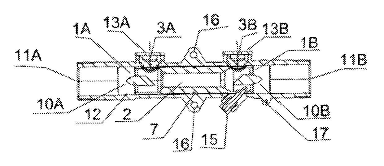
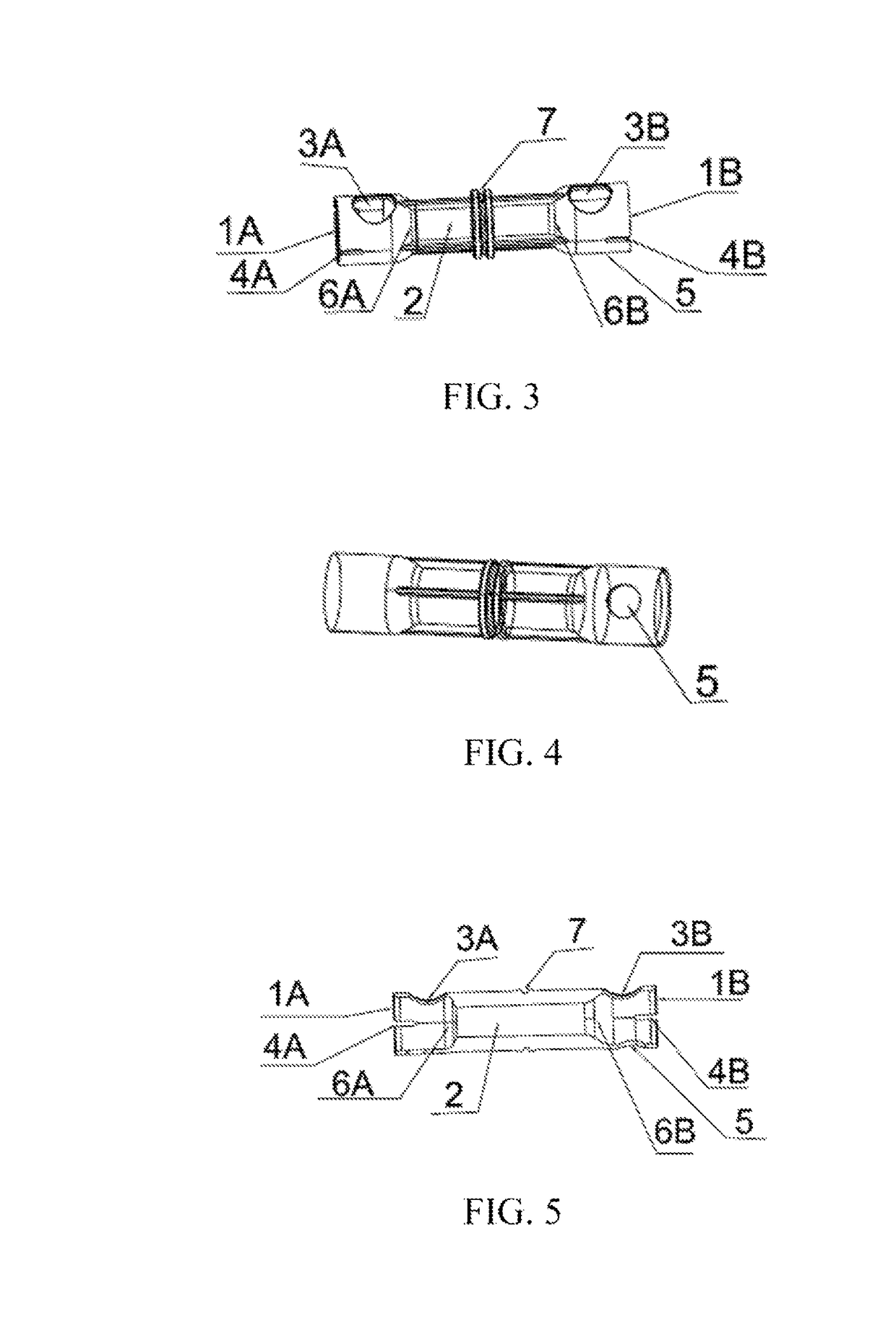
[0035]Referring to FIGS. 3-5, an ultrasonic flow tube includes a water inlet (1A), a water outlet (1B), a sound channel (2), a first mounting hole (3A) for fixing a first ultrasonic transducer, and a second mounting hole (3B) for fixing a second ultrasonic transducer. The water inlet (1A) defines a first fixing room which is a first fixing groove (4A). The first fixing groove (4A) is positioned at a side of the water inlet (1A). The water outlet (1B) defines a second fixing room which is a second fixing groove (4B). The second fixing groove (4B) is positioned at a side of the water outlet (1B). The water outlet (1B) also defines an installation hole (5) for installing a temperature sensor. The installation hole (5) is positioned at a bottom of the water outlet (1B). An entrance (6A) and an exit (6B) are defined at opposite ends of the sound channel (2). The entrance (6A) is equipped with a chamfer which can make the flow more smoothly and restrain turbulent flow....

second embodiment

The Second Embodiment

[0037]Referring to FIGS. 6-7, an ultrasonic flow tube includes a water inlet (1A), a water outlet (1B), a sound channel (2), a first mounting hole (3A) for fixing a first ultrasonic transducer, and a second mounting hole (3B) for fixing a second ultrasonic transducer. The water inlet (1A) defines a first fixing room which is a first fixing groove (4A). The first fixing groove (4A) is positioned at a bottom of the water inlet (1A). The water outlet (1B) defines a second fixing room which is a second fixing groove (4B). The second fixing groove (4B) is positioned at a bottom of the water outlet (1B). An entrance (6A) and an exit (6B) are defined at opposite ends of the sound channel (2). The entrance (6A) is equipped with a chamfer which can make the flow more smoothly and restrain turbulent flow. An installation groove (7) for installing a seal ring is defined at an external sidewall of the ultrasonic flow tube. The seal ring is configured to seal the ultrasonic ...

third embodiment

The Third Embodiment

[0040]Referring to FIGS. 8-11 together with FIGS. 3-5, an ultrasonic flow tube assembly includes an ultrasonic flow tube, a first reflector (8A), and a second reflector (8B). The ultrasonic flow tube includes a water inlet (1A), a water outlet (1B), a sound channel (2), a first mounting hole (3A) for fixing a first ultrasonic transducer, and a second mounting hole (3B) for fixing a second ultrasonic transducer. The water inlet (1A) defines a first fixing room which is a first fixing groove (4A). The first fixing groove (4A) is positioned at a side of the water inlet (1A). The water outlet (1B) defines a second fixing room which is a second fixing groove (4B). The second fixing groove (4B) is positioned at a side of the water outlet (1B). The water outlet (1B) also defines an installation hole (5) for installing a temperature sensor. The installation hole (5) is positioned at a bottom of the water outlet (1B). An entrance (6A) and an exit (6B) are defined at oppos...


PUM


Abstract

An ultrasonic flow sensor assembly includes an ultrasonic flow tube, a first reflector, a second reflector, a first ultrasonic transducer, a second ultrasonic transducer, a temperature sensor, and a tube section for accommodating the ultrasonic flow tube. The ultrasonic flow tube includes a water inlet for fixing the first reflector, a water outlet for fixing the temperature sensor and the for fixing the second reflector, a sound channel, a first mounting hole for fixing the first ultrasonic transducer, and a second mounting hole for fixing the second ultrasonic transducer. An entrance of the sound channel is equipped with a chamfer which can make the flow more smoothly and restrain turbulent flow. An installation groove for installing a seal ring is defined at an external sidewall of the ultrasonic flow tube. The ultrasonic flow tube is made of plastic or ceramic.

Description

[0001]This is a continuation of PCT application No. PCT / CN2013 / 080189, filed on Jul. 26, 2013. This application claims the priority of Chinese patent application number 201520064948.3, filed on Jan. 30, 2015 and of Chinese patent application number 201520064966.1, filed on Jan. 30, 2015, the entire contents of which are incorporated herein by reference.FIELD OF THE DISCLOSURE[0002]The present disclosure relates to flow measurement technologies, and particularly, to an ultrasonic flow tube, an ultrasonic flow tube assembly having the ultrasonic flow tube, an ultrasonic flow sensor having the ultrasonic flow tube assembly, and an ultrasconic flow meter having the ultrasonic flow sensor.BACKGROUND OF THE DISCLOSURE[0003]With the development of society and the advancement of technology, environment protection and energy saving becomes more important, for example, people put more emphasis on saving daily energy, such as, electricity, water, and fuel gas. Energy measurement plays an impor...

Claims


Application Information

Patent Timeline
Patent Type & Authority Patents(United States)
IPC IPC(8): G01F1/66G01F15/18G01F15/00
CPCG01F15/185G01F15/00G01F1/667G01F1/662
Inventor ZHANG, FENGMINYU, ZHONGKUIWANG, YONGLONGLI, LIN
Owner ZHEJIANG JOY ELECTRONICS TECH
Why Eureka
Try Eureka