Stenosis therapy planning

a stenosis and therapy technology, applied in the field of stenosis therapy planning, can solve the problems of insufficient accuracy of arterial dimensions and/or stenosis degree, inability to accurately and/or effectively plan interventional therapy, follow-up interventional procedure,

Active Publication Date: 2018-08-21
KONINK PHILIPS ELECTRONICS NV
View PDF30 Cites 12 Cited by
  • Summary
  • Abstract
  • Description
  • Claims
  • Application Information

AI Technical Summary

Benefits of technology

[0007]Embodiments according to the present invention are directed to a method for planning an arterial stenosis therapy comprising receiving a first volumetric data set by medical imaging of at least part of an artery, said part comprising a stenosis; receiving at least one two-dimensional image data of the stenosis; determining a first arterial pressure drop around the stenosis; generating a second volumetric data set by registering the at least one two-dimensional image data with the first volumetric data set; generating a third volumetric data set by simulating a geometry modification of the stenosis in the second volumetric data set; and estimating a second arterial pressure drop around the stenosis in the third volumetric data set. In this method three-dimensional imaging data obtained by non-invasive medical imaging of a stenosed artery is combined with a set of two-dimensional images of the same artery, resulting in a data set which represents the actual stenosed artery closer than a data set based on either of the individual data sets. A simulation of modification of a stenosis geometry is more reliable, since the combined data set provides a much more realistic starting point, especially when combined with determined arterial pressure data.
[0008]Another embodiment of the present invention is directed towards using the first arterial pressure drop as a starting point in the estimation of the second arterial pressure drop. This allows for an even further improved simulation of the second arterial pressure drop, since it is based on actual arterial pressure data.
[0010]Another embodiment of the present invention is directed towards that the at least one two-dimensional image data comprises at least two two-dimensional image data which were acquired along different projection directions with regard to the stenosis. This allows for imaging at least partially obscured tissue and for improved matching the at least two-dimensional image data with the first volumetric data.
[0013]Another embodiment of the present invention is directed towards the method further comprising displaying each second arterial pressure drop for each of the at least two third volumetric data sets. Displaying all the estimated arterial pressure drops allows a user, such as a physician, to conveniently see the effect of each geometry simulation, which will assist him in select the optimal stenosis therapy.
[0018]Still further aspects and embodiments of the present invention will be appreciated by those of ordinary skill in the art upon reading and understanding the following detailed description. Numerous additional advantages and benefits will become apparent to those of ordinary skill in the art upon reading the following detailed description of preferred embodiments.

Problems solved by technology

Unfortunately it is not always possible to accurately and / or effectively plan the interventional therapy, since it is not always possible to determine the effect of the therapy beforehand.
This may result in non-optimal results or may even require a follow-up interventional procedure, which, in both cases, is not in a patient's best interest.
A drawback of such a procedure is that arterial dimensions and / or degree of stenosis are modeled with insufficient accuracy due to imaging errors (artifacts) and / or because certain assumptions made may be incorrect.
Medical imaging of cardiac arteries is particularly complicated and prone to even more artifacts due to constant movement of the cardiac area.
Further modeling is necessary to overcome this, for which further assumptions and corrections need to be made, causing further risks of not accurately determining the arterial dimensions and degree of stenosis before or after the virtual stent is placed, and, as a consequence, a physician may not select an optimal treatment.

Method used


Image

  • Stenosis therapy planning
  • Stenosis therapy planning
  • Stenosis therapy planning

Examples


Embodiment Construction

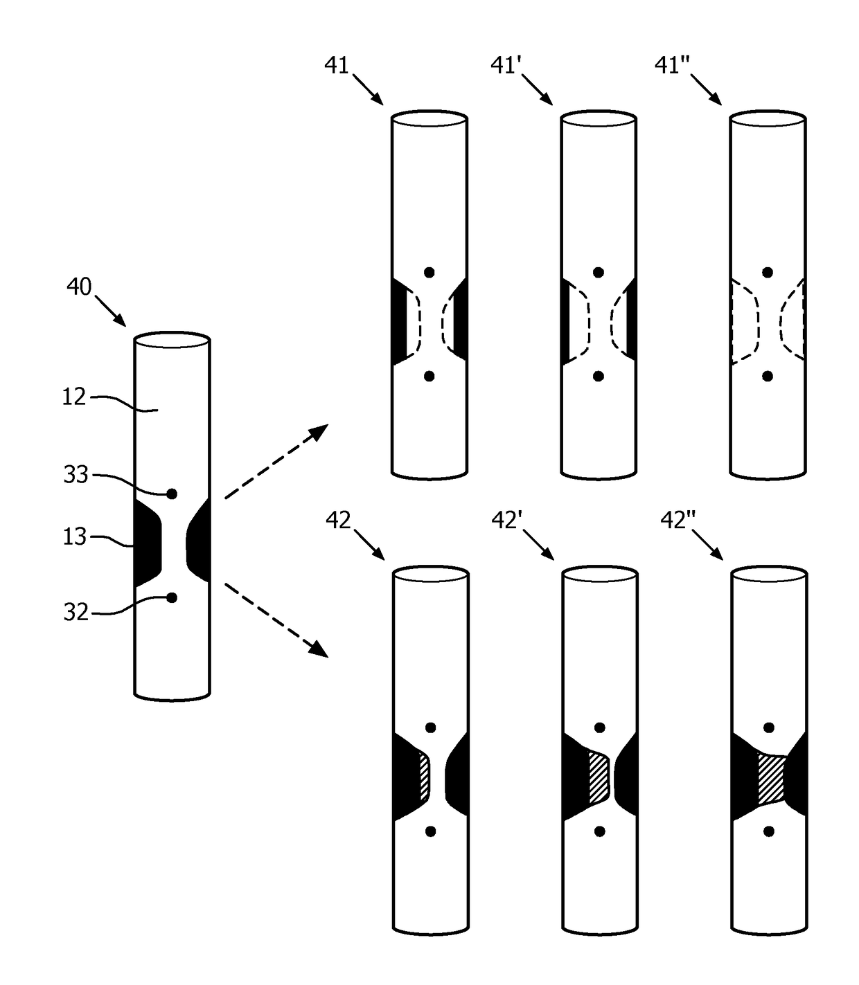
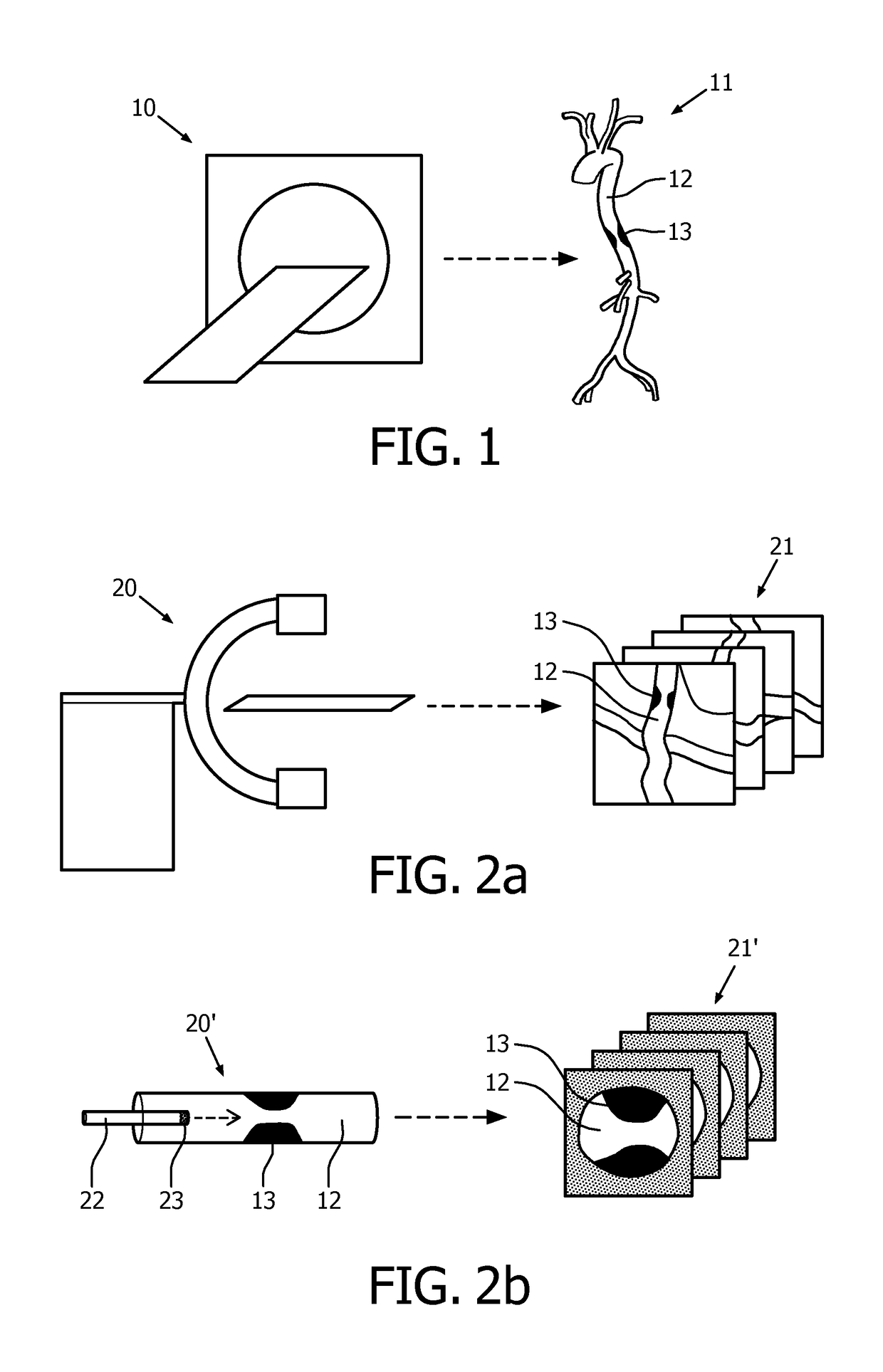
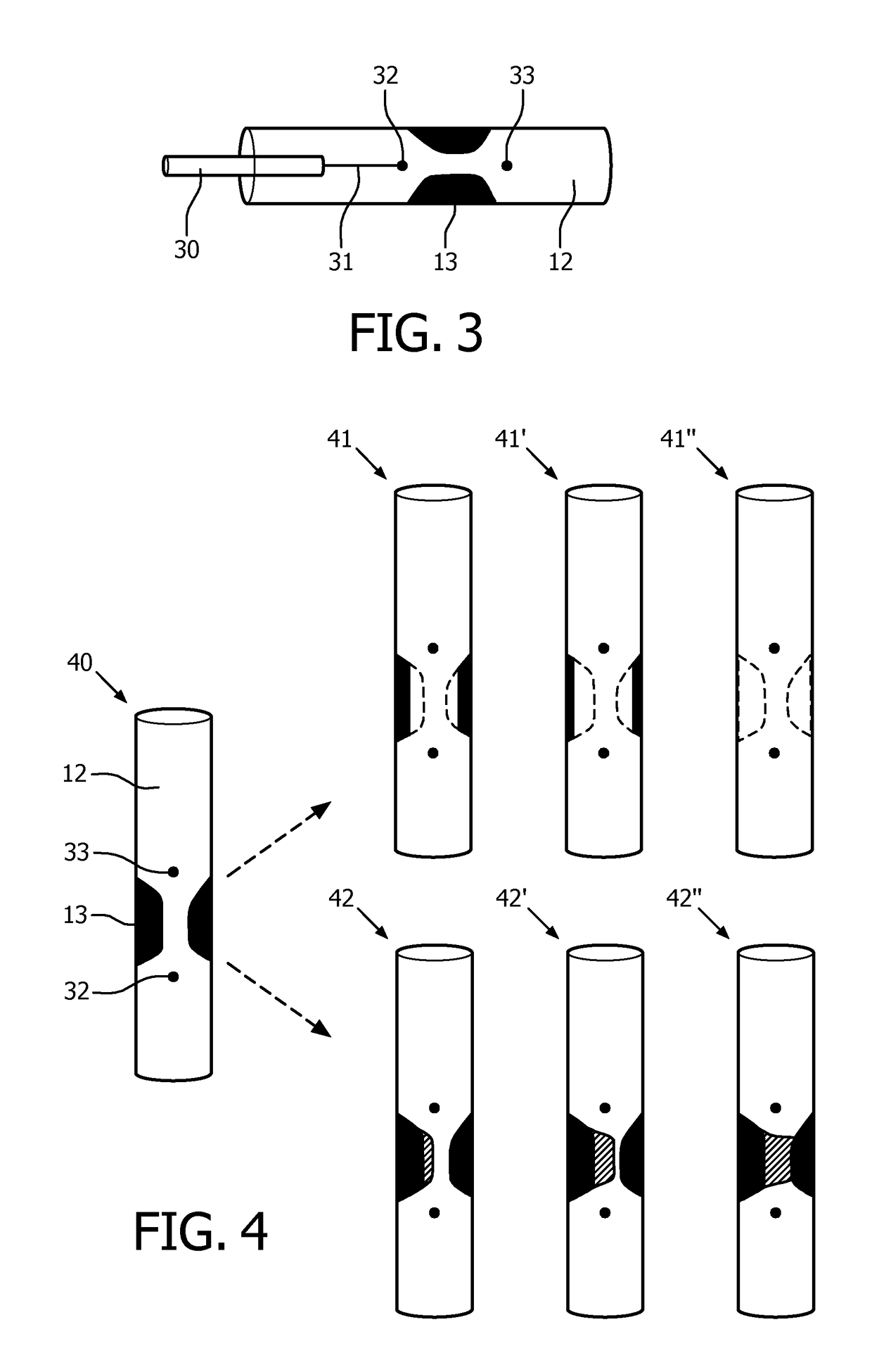
[0029]A physician confronted with a patient with a known or suspected arterial stenosis, in particular a coronary artery stenosis, has several treatment options to treat the stenosis by reducing or removing the stenosis, including, but not limited to placing a stent, a ballooning procedure, bypass or other surgery, prescribing medication or a diet, advice lifestyle changes or even take a decision to perform no action at that moment and keep monitoring the situation over time and defer treatment to a later moment in time. If the physician has access to a reliable prediction of an outcome of one or more treatment options, he may better plan and select a most effective treatment.

[0030]In the present invention the patient undergoes at least two imaging procedures: a (non-invasive) medical imaging procedure to obtain a volumetric (three-dimensional) data set and a medical imaging procedure to obtain two-dimensional images along different projection directions. Furthermore, an arterial pr...


PUM


Abstract

The present invention relates to stenosis therapy planning. A first volumetric data set is received by medical imaging of at least part of an artery comprising a stenosis. At least one two-dimensional image data (of the stenosis is received. A first arterial pressure drop is determined around the stenosis. A second volumetric data set is generated by registering the at least one two-dimensional image data with the first volumetric data set. A third volumetric data set is generated by simulating a geometry modification of the stenosis in the second volumetric data set and a second arterial pressure drop is estimated around the stenosis in the third volumetric data set.

Description

CROSS-REFERENCE TO PRIOR APPLICATIONS[0001]This application is the U.S. National Phase application under 35 U.S.C. § 371 of International Application No. PCT / EP2014 / 057758, filed on Apr. 16, 2014, which claims the benefit of European Patent Application No. 13164233.2, filed on Apr. 18, 2013. These applications are hereby incorporated by reference herein.FIELD OF THE INVENTION[0002]The present invention generally relates to stenosis therapy planning, in particular interventional stenosis therapy planning, such as virtual stenting.BACKGROUND OF THE INVENTION[0003]Degenerative stenosis is the second most common cardiovascular disease with an incidence of 2-7% in the Western European and North American populations aged beyond 65 years, as described in G. M. Feuchtner, W. Dichtl, et al. “Multislice Computed Tomography for Detection of Patients With Aortic Valve Stenosis and Quantification of Severity”, Journal of the American College of Cardiology 2006, 47 (7), 1410-1417. In the context ...

Claims


Application Information

Patent Timeline
Patent Type & Authority Patents(United States)
IPC IPC(8): A61B6/03A61B5/026A61B5/0215A61B5/02A61B5/00A61B8/14A61B5/055A61B90/00A61B34/10
CPCA61B5/02007A61B5/026A61B5/0215A61B5/6851A61B5/742G16H50/50A61B6/032A61B6/037A61B8/14A61B2034/105A61B2090/3782A61B5/055A61B2090/364A61B2034/104A61B2034/107
Inventor GRASS, MICHAELSCHAEFER, DIRKSCHMITT, HOLGER
Owner KONINK PHILIPS ELECTRONICS NV
Why Eureka
Try Eureka