Aircraft system

a technology of aircraft and remote control, applied in the field of aircraft systems, can solve the problems of insufficient stability and reliability of the signal transmission between the aircraft and the remote control, the user's difficulty in observing images, and the process is susceptible to interference, so as to achieve convenient use

Active Publication Date: 2018-08-21
YUNEEC TECH CO LTD
View PDF10 Cites 4 Cited by
  • Summary
  • Abstract
  • Description
  • Claims
  • Application Information

AI Technical Summary

Benefits of technology

[0006]The remote control provided by the present invention comprises the display for displaying the image signals; while controlling the aircraft apparatus through the remote control, the operator is capable of intuitively observing images captured by the image capturing device, thus providing convenience for the user. Moreover, the remote control provided by the present invention utilizes two communication circuits, so two antennas are provided for respectively communicating with an aircraft unit and the image capturing device, the transmission of the control signals is independent and not interferential from the transmission of the image signals, thus the signal transmission is more stable and reliable.
[0015]The positive effects of the present invention are that: in the aircraft system provided by the present invention, the control signals for controlling the aircraft and the image signals transmitted by the image capturing device are not interferential from each other to stabilize the signal transmission; the display is capable of directly displaying the image signals to convenient for the user. The image signals are transmitted through the 5.8 GHz communication circuit, so that the images displayed by the display become more fluent.

Problems solved by technology

In the prior art, the aircraft is usually capable of achieving aerial photography, and the images acquired by the aircraft need to be displayed by a separate display device, so that it is difficult for the user to observe the images.
Moreover, the image signals obtained by the aircraft in the transmission process are susceptible to be interfered, so the signal transmission between the aircraft and the remote control is not stable and reliable enough.

Method used


Image

  • Aircraft system
  • Aircraft system
  • Aircraft system

Examples


Embodiment Construction

[0022]The present invention is further more clearly and completely explained with accompanying preferred embodiments and drawings as follows.

[0023]In description of the present invention, it should be understood that the orientation or position relationship described by words such as “upper”, “lower”, “front”, “rear”, “left”, “right”, “vertical”, “horizontal”, “top”, “bottom”, “internal” and “external” is based on the accompanying drawing, which is only for simplifying the description of the present invention, not for indicating or implying a specific orientation, and a structure and an operation at the specific orientation of the devices or parts. Thus, the above words are not the limitations of the present invention.

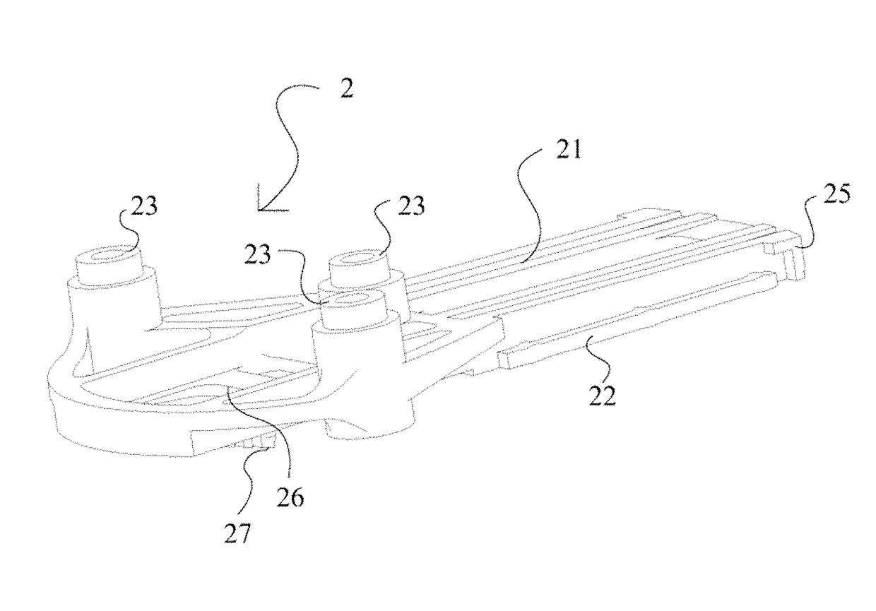
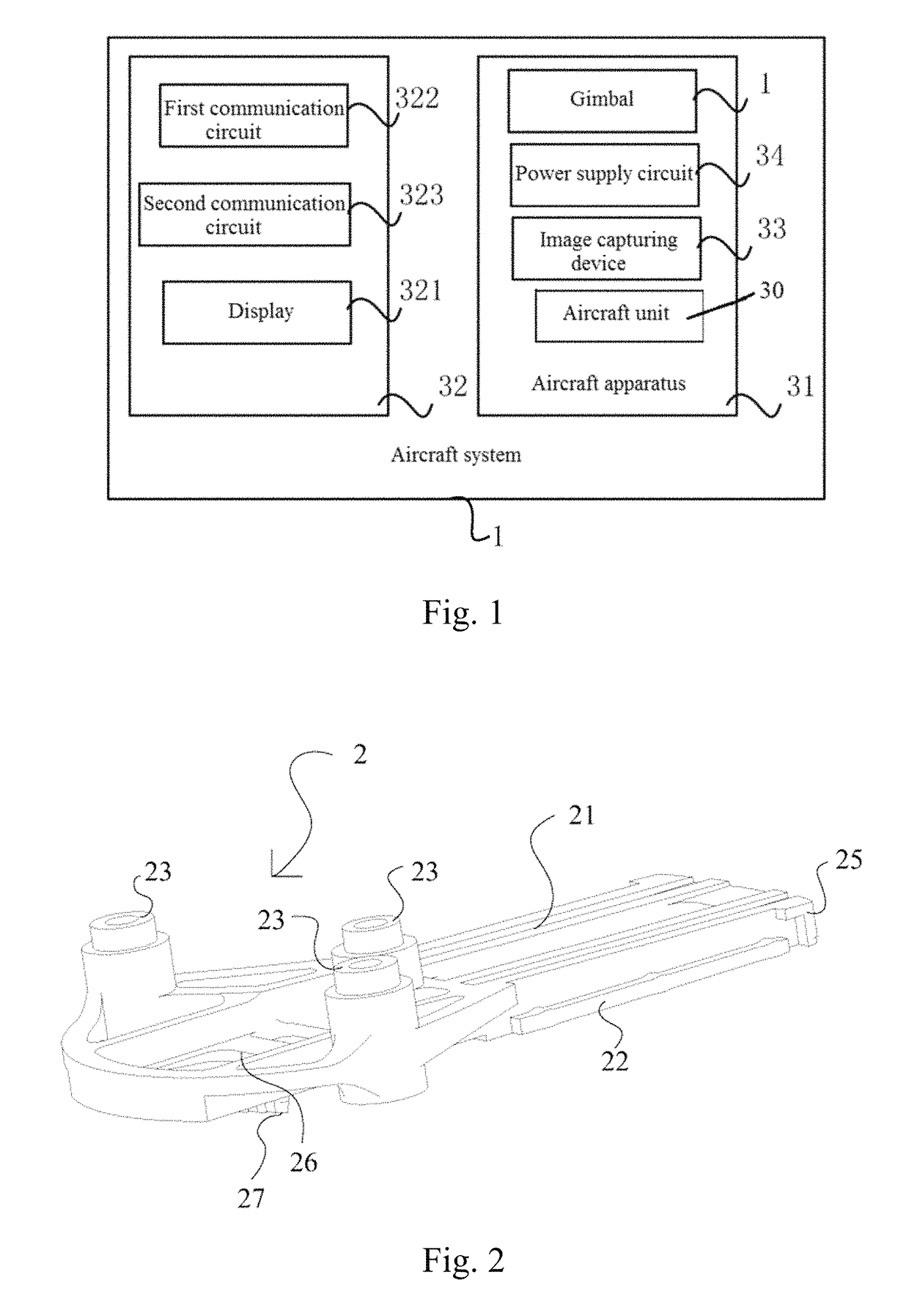
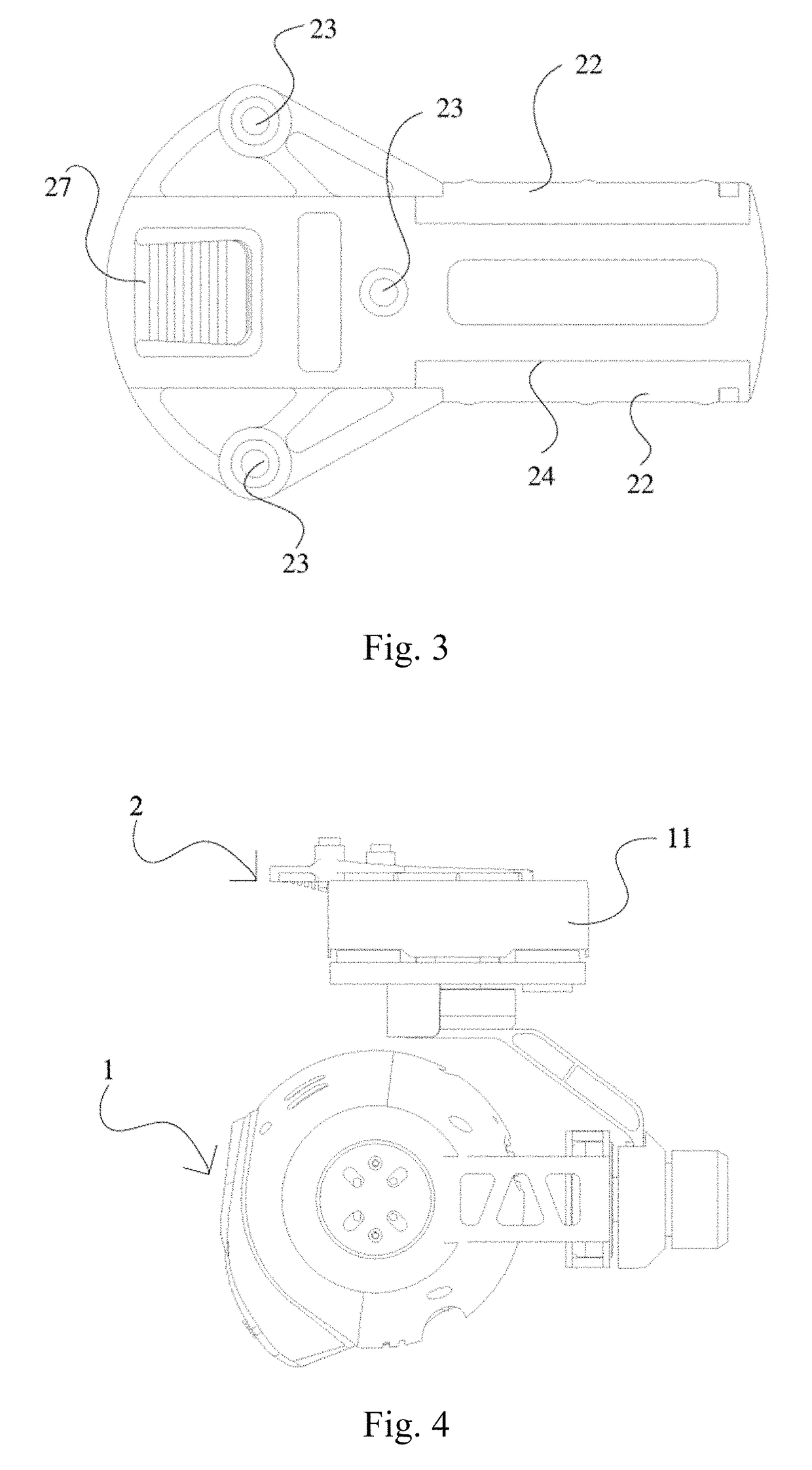
[0024]Referring to FIGS. 1-5, the present invention provides an aircraft system which comprises an aircraft apparatus 31 comprising an image capturing device 33 and a remote control 32, wherein: the remote control 32 comprises a display 321, a first communication circu...


PUM


Abstract

An aircraft system (1) includes an aircraft apparatus (31) including an image capturing device (33) and a remote control (32). The remote control (32) includes a display (321), a first communication circuit (322) adapted for transmitting aircraft control signals to the aircraft apparatus (31), and a second communication circuit (323) adapted for receiving image signals of the image capturing device. The display (321) is adapted for displaying the image signals.

Description

CROSS REFERENCE OF RELATED APPLICATION[0001]This is a U.S. National Stage under 35 U.S.C. 371 of the International Application PCT / CN2015 / 097804, filed Dec. 18, 2015, which claims priority under 35 U.S.C. 119(a-d) to CN201420814036.9, filed Dec. 18, 2014. The full text of the above-mentioned Chinese patent application is included in the present invention.BACKGROUND OF THE PRESENT INVENTIONField of Invention[0002]The present invention relates to an aircraft system.Description of Related Arts[0003]In the prior art, the aircraft is usually capable of achieving aerial photography, and the images acquired by the aircraft need to be displayed by a separate display device, so that it is difficult for the user to observe the images. Moreover, the image signals obtained by the aircraft in the transmission process are susceptible to be interfered, so the signal transmission between the aircraft and the remote control is not stable and reliable enough.SUMMARY OF THE PRESENT INVENTION[0004]A te...

Claims


Application Information

Patent Timeline
Patent Type & Authority Patents(United States)
IPC IPC(8): G03B15/00B64D47/08H04N5/232F16M11/20F16M11/08
CPCB64D47/08F16M11/08H04N5/23206G03B15/006F16M11/2035H04N7/18G03B17/561H04N7/185G03B2206/00F16M11/041F16M11/10F16M11/2071F16M13/02H04N23/661H04N23/63B64U20/87
Inventor TIAN, YUJIANG, WENYAN
Owner YUNEEC TECH CO LTD
Why Eureka
Try Eureka